
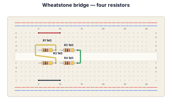
The bridge circuit is made up of four resistors connected as shown on fig. A. The circuit has two input terminals and two output terminals. In DC applications, the output terminals are connected to some source of DC voltage such as battery. Often a meter is connected across the output terminals as shown in fig. B
ENGINEERING DRAWING ARCHIVE · REAL SPECS
Engineering Diagram Examples from Real Specifications
Browse eligible circuit, ladder, single-line, P&ID, breadboard, timing, and logic drawings with their original prompts.
Browse 525 real creationsCOMMUNITY OUTPUTS · EXACT PROMPTS
Breadboard Diagrams
Showing 1–17 of 17. No stock examples or system defaults. Choose a tool, study a real result, then reopen its prompt as your starting point.
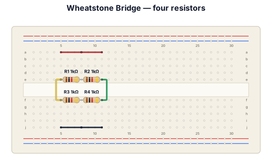
The bridge circuit is made up of four resistors connected in a wheatstone bridge. The circuit has two input terminals and two output terminals.
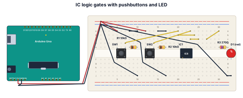
Draw a top-down view of a breadboard powered by an Arduino Uno. Show only the red wire from Arduino 5V to the breadboard positive rail (+) and the black wire from Arduino GND to the negative rail (-). Do not connect any other Arduino pins. Power Connections: Connect Pin 14 (VCC) of the IC to the +5V rail. Connect Pin 7 (GND) of the IC to the GND rail. Logic Input Circuits (Active-High Logic): Input A: Use a pushbutton connected between the +5V rail and the input pins (Pins 1 & 2 tied together for Gate 1). Connect a 10kΩ pull-down resistor from this input node to GND (ensures released = 0, pressed = 1). (Note: If no pushbutton is available, connect a jumper wire directly from +5V to the input node instead). Input B: Use a second pushbutton connected between the +5V rail and the second input pins (Pins 4 & 5 tied together for Gate 2). Connect a 10kΩ pull-down resistor from this input node to GND (ensures released = 0, pressed = 1). (Note: If no pushbutton is available, connect a jumper wire directly from +5V to the input node instead). Gate Interconnections: Wire Pin 3 (Output of NOT 1) to Pin 9 (Input 1 of Gate 3). Wire Pin 6 (Output of NOT 2) to Pin 10 (Input 2 of Gate 3). Logic Output Circuit: Place one red LED directly on the breadboard to visualize output (on = 1, off = 0). Connect the anode (longer leg) directly to Pin 8 (Output of Gate 3). Connect the cathode (shorter leg) through a single 270Ω resistor directly to the GND rail to protect the LED. Layout Constraints: Remove any bottom bridge wires or redundant components. Keep the layout completely minimal and clean.
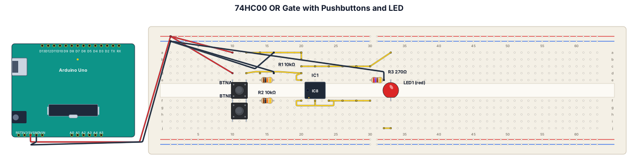
Draw a top-down view of a breadboard with an Arduino Uno placed next to it. Hide most of the Arduino pins. Show only the red wire connecting the 5V pin to the positive rail (+) of the breadboard, and the black wire connecting the GND pin to the negative rail (-) of the breadboard. No other Arduino pins should be connected. Circuit Power (Breadboard): Connect Pin 14 (VCC) of the 74HC00 IC to the +5V power rail using a short red wire. Connect Pin 7 (GND) of the 74HC00 IC to the GND rail using a short black wire. Input Logic (Pushbuttons A and B): Pushbutton A (Input A): Connected on one side to +5V. Connected on the other side to Pins 1 and 2 of the 74HC00 (tied together) to create a NOT gate. Include a 10kΩ pull-down resistor connected between this junction and the GND rail. Pushbutton B (Input B): Connected on one side to +5V. Connected on the other side to Pins 4 and 5 of the 74HC00 (tied together) to create the second NOT gate. Include a second 10kΩ pull-down resistor connected between this junction and the GND rail. Internal Connections (Forming the OR Gate): Connect Pin 3 (Output of the 1st NOT gate) to Pin 9 (Input 1 of the 3rd NAND gate). Connect Pin 6 (Output of the 2nd NOT gate) to Pin 10 (Input 2 of the 3rd NAND gate). Output Logic (LED): Place a single red LED directly on the breadboard. Connect the anode (longer leg) of the LED directly to Pin 8 (Output of the 3rd NAND gate). Connect the cathode (shorter leg) of the LED to a single 270Ω resistor, which in turn connects to the GND rail. Simplification & Cleanliness: Do not place any extra components, wires, or resistors at the bottom of the breadboard. Keep the diagram clean, minimal, and easy to read.
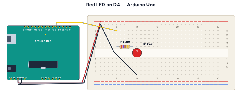
An Arduino Uno breadboard diagram for one red LED on digital pin 4 through a 270 ohm resistor, with the ground rail connected back to Arduino GND.
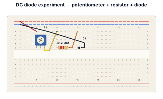
Create a realistic top-down breadboard wiring diagram for a simple DC diode experiment. Components: - One B10K 10 kΩ three-pin potentiometer - One 2.2 kΩ fixed resistor - One 1N4004 diode - One adjustable DC power supply - Jumper wires Connect in series: DC positive → potentiometer used as a variable resistor → 2.2 kΩ resistor → diode → DC negative. Label the potentiometer terminals, resistor value, diode anode (A), and cathode (K). Show numbered breadboard rows, exact wire endpoints, and a complete closed circuit. Use a real breadboard layout, not a schematic. Do not add buttons or unrelated components. If exact hole positions are uncertain, label them as provisional. Generate a clear, simple image with no extra text.
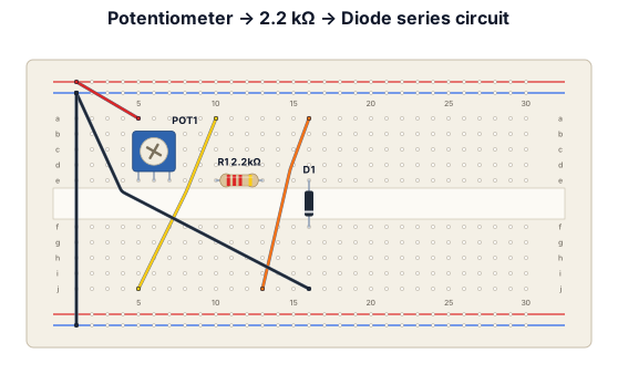
Fix the existing breadboard diagram. Do not invent a new circuit. Required components: - One real 3-terminal B10K (10 kΩ linear) potentiometer, not a push button or generic variable-resistor icon. - One fixed resistor labeled exactly R = 2.2 kΩ, not 1 kΩ. - One rectifier diode with clearly marked anode A and cathode K. - One adjustable DC power supply. Required series path: DC positive → potentiometer used as a variable resistor → 2.2 kΩ resistor → diode → DC negative. Show the actual potentiometer terminals and clearly identify which two terminals are used. If using the center wiper and one outer terminal, show their exact connections. Use a realistic solderless breadboard with numbered rows and columns. Show every jumper wire endpoint. Ensure each connection matches the intended circuit nodes and does not accidentally short across internally connected breadboard holes. Remove all unrelated components and incorrect labels. Do not label the resistor 1 kΩ. Do not generate a push button in place of the potentiometer. If exact physical pin positions cannot be verified, mark them as unverified instead of inventing coordinates. Output only a clear, top-down breadboard wiring diagram with a numbered assembly guide.
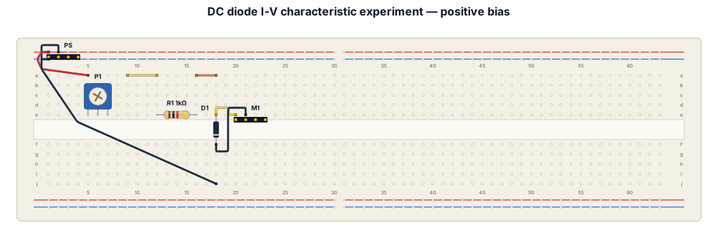
Create a clear, realistic, top-down breadboard wiring diagram for a DC diode I-V characteristic experiment. Components: - One B10K (10 kΩ linear) potentiometer - One fixed series resistor R (its resistance value must be confirmed before final wiring) - One rectifier diode, such as 1N4004 - An adjustable DC power supply - Jumper wires - A digital multimeter for measuring diode voltage and circuit current Follow this circuit topology: DC supply → potentiometer used as a variable resistor → fixed resistor R → diode → DC supply return. Show: 1. A realistic solderless breadboard with numbered rows and labeled columns. 2. Exact breadboard holes for every component lead and jumper wire. 3. The potentiometer's three terminals, clearly identifying the two outer terminals and the center wiper. 4. The diode anode (A) and cathode (K), including the silver-band marking. 5. Red and black power connections, colored jumper wires, and a wiring legend. 6. The positive-bias and reverse-bias configurations as separate diagrams. 7. A step-by-step assembly guide with a final wiring checklist. IMPORTANT: Do not invent component pinouts or claim that unverified breadboard holes are electrically correct. Clearly mark any assumptions and ask for missing component details before assigning exact row and column coordinates. Keep the power supply switched off during assembly. Generate a practical breadboard layout, not only a schematic symbol drawing.
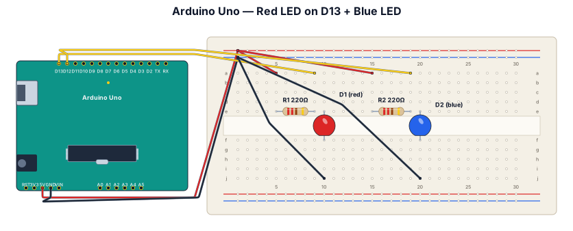
An Arduino Uno breadboard diagram for one red LED on digital pin 13 through a 220 ohm resistor, with the ground rail connected back to Arduino GND. udd a random blue led
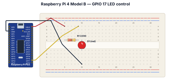
Create a breadboard wiring diagram showing a "Raspberry Pi 4 Model B" connected to a breadboard, with GPIO 17 controlling a red LED through a 220-ohm resistor. Must remember the board is "Raspberry Pi 4 Model B" not pico
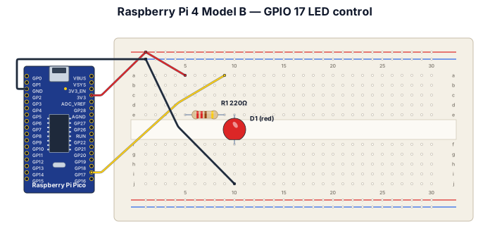
Create a breadboard wiring diagram showing a "Raspberry Pi 4 Model B" connected to a breadboard, with GPIO 17 controlling a red LED through a 220-ohm resistor.
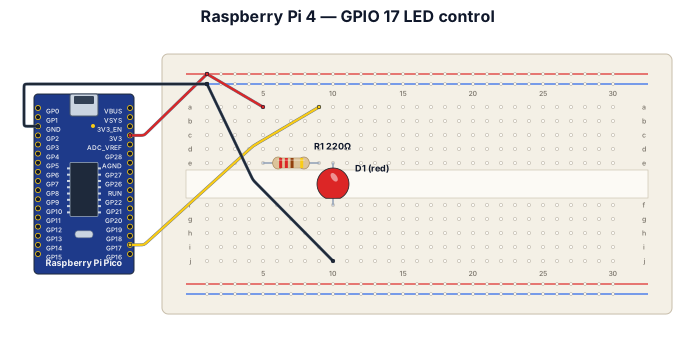
Create a breadboard wiring diagram showing a Raspberry Pi 4 Model B connected to a breadboard, with GPIO 17 controlling a red LED through a 220-ohm resistor.
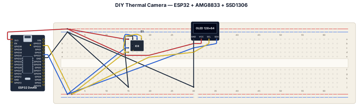
Create a realistic, beginner-friendly breadboard wiring diagram for a DIY thermal camera. COMPONENTS: 1. ESP32 DevKit V1 (ESP-WROOM-32) 2. AMG8833 Grid-EYE 8×8 infrared thermal sensor breakout module 3. SSD1306 0.96-inch monochrome OLED display, 128×64, I2C, 4 pins 4. One solderless breadboard 5. Male-to-male jumper wires NO SOLDERING. All modules must have pre-installed header pins compatible with the breadboard. EXACT CONNECTIONS: ESP32 3V3 → AMG8833 VIN/VCC and OLED VCC ESP32 GND → AMG8833 GND and OLED GND ESP32 GPIO21 → AMG8833 SDA and OLED SDA ESP32 GPIO22 → AMG8833 SCL and OLED SCL Use the ESP32's 3.3V supply. Verify the voltage requirements and pin labels of the actual breakout modules before building. DIAGRAM REQUIREMENTS: - Show the actual ESP32 DevKit V1 board and its labeled pins. - Show a full-size solderless breadboard. - Show the AMG8833 sensor module and SSD1306 OLED module. - Use red wires for 3.3V, black wires for GND, blue wires for SDA, and yellow wires for SCL. - Clearly label every connection and GPIO number. - Route wires neatly and avoid crossing wires where possible. - Show both I2C devices connected in parallel to the same SDA and SCL lines. - Do not invent extra components or connections. - If a component pinout cannot be verified, mark it as requiring verification. OUTPUT: Generate a physical breadboard layout, not just a symbolic electrical schematic. Include a pin-to-pin wiring table below the diagram. Make the diagram readable for a beginner assembling the circuit without soldering. This is a reference design. Do not claim the circuit has been physically tested.
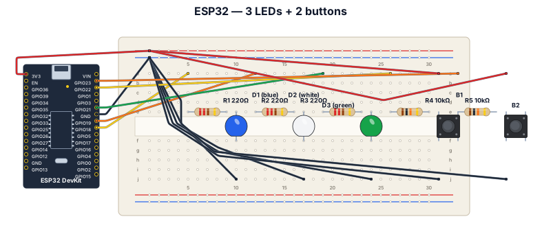
A ESP32 development board, wired to 3 leds (blue, white, green) through pins D18, 19 & 21, passing to ground through 220ohm resistors. Pins D22 & 23 go out to 2 buttons, these go to ground through 10kohms resistors. The board outputs positive current via 3v3, this only powers the buttons.
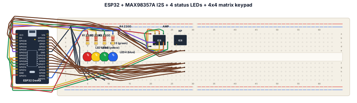
esp32 connected to a max98357A i2s audio amplifier and 4 status leds. 4x4 matrix push buttons connected to the pins on the left side of the esp32
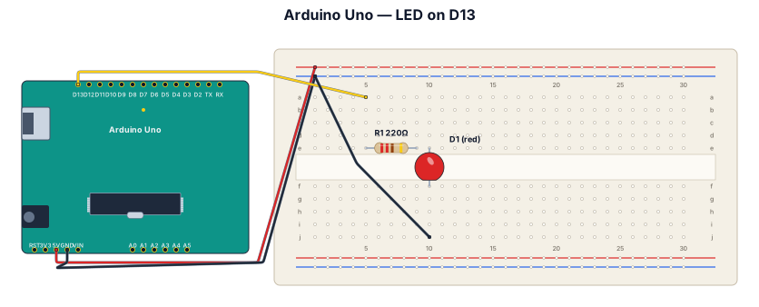
An Arduino Uno breadboard diagram for one red LED on digital pin 13 through a 220 ohm resistor, with the ground rail connected back to Arduino GND.
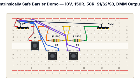
Create a beginner-friendly breadboard circuit based on an intrinsically safe barrier demonstration. Use a 10 V DC power supply, one 150 Ω resistor, one 50 Ω resistor, and three normally-open momentary push buttons. Do not use Arduino or any microcontroller. Show the exact breadboard hole connections, power rails, jumper wires, resistor positions, and multimeter probe positions. Label every component and connection clearly. Arrange the circuit as follows: push button S1 in series with the supply input, followed by the 150 Ω resistor and then the 50 Ω resistor. Connect push button S2 from the junction between the two resistors to the negative rail. Connect push button S3 from the output after the 50 Ω resistor to the negative rail. Connect the power supply negative terminal to the negative rail. Show how to measure output voltage using the multimeter. Generate an actual breadboard layout, not only a circuit schematic. Explain how the circuit behaves when each button is pressed. Flag any floating output or excessive current risks and recommend safe low-current test conditions.