
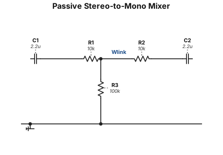
Draw a passive stereo-to-mono audio mixer using only resistors, nonpolar capacitors, ground symbols, and labeled connection points. Do not draw connector symbols. LEFT connects through C1, 2.2 microfarads, then R1, 10 kilohms, to MONO. RIGHT connects through C2, 2.2 microfarads, then R2, 10 kilohms, to the same MONO node. R3, 100 kilohms, connects MONO to GND. OUT connects directly to MONO. Place LEFT and RIGHT on the left in separate horizontal rows. Place OUT on the right. Show a junction dot where the two branches and R3 meet. Label that junction MONO. Preserve all stated component values exactly.
ENGINEERING DRAWING ARCHIVE · REAL SPECS
Engineering Diagram Examples from Real Specifications
Browse eligible circuit, ladder, single-line, P&ID, breadboard, timing, and logic drawings with their original prompts.
Browse 532 real creationsCOMMUNITY OUTPUTS · EXACT PROMPTS
Circuit Diagram Online
Showing 1–15 of 15. No stock examples or system defaults. Choose a tool, study a real result, then reopen its prompt as your starting point.
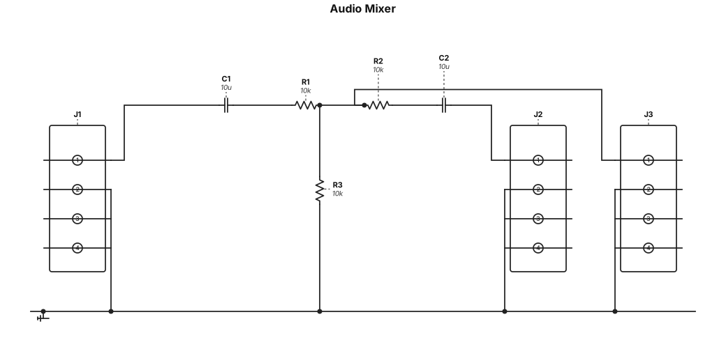
Keep the existing Audio Mixer circuit and component values. Replace J1 LEFT, J2 RIGHT, and J3 OUT with two-pin connectors only. Pin 1 is signal and pin 2 is ground. J1 pin 1 connects through C1 and R1 to MONO. J2 pin 1 connects through C2 and R2 to MONO. J3 pin 1 connects directly to MONO. R3 connects MONO to ground. Pin 2 of all three connectors connects to ground. Label the junction of R1, R2, R3 and J3 pin 1 as MONO. Arrange the branches to avoid wire crossings. Show junction dots wherever wires connect. Use nonpolar capacitor symbols for C1 and C2.
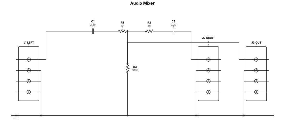
An audio mixer with two input connectors labeled LEFT and RIGHT. Each input connects through a 2.2 microfarad capacitor and then a 10 kilohm resistor to a shared node labeled MONO. A 100 kilohm resistor connects MONO to ground. An output connector connects to MONO. Use standard schematic symbols.
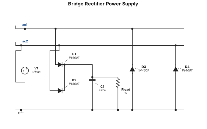
A bridge rectifier power supply with a 12 VAC source, four 1N4007 diodes, a 470 microfarad smoothing capacitor, and a 1 kilohm load.
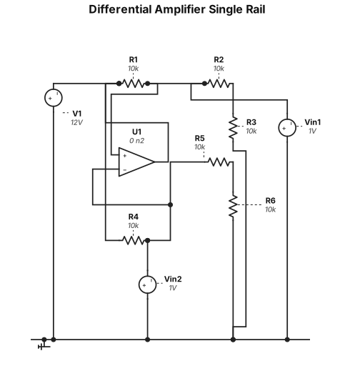
Differential amplifier with O.A. single rail
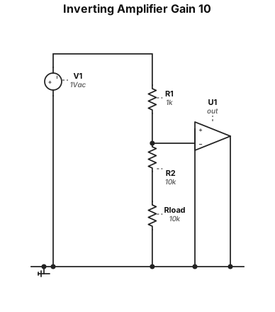
Draw inverting amplifier with gain =10
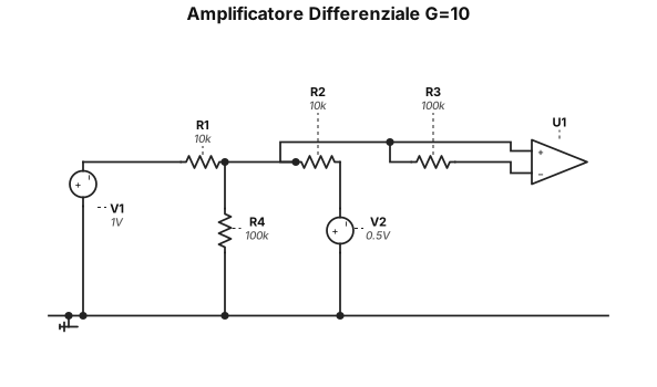
crea un amplificatore differenziale di G 10 con la retroazione sull'ingresso invertente
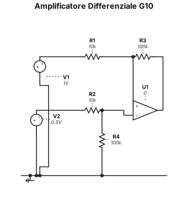
crea un amplificatore differenziale di G 10
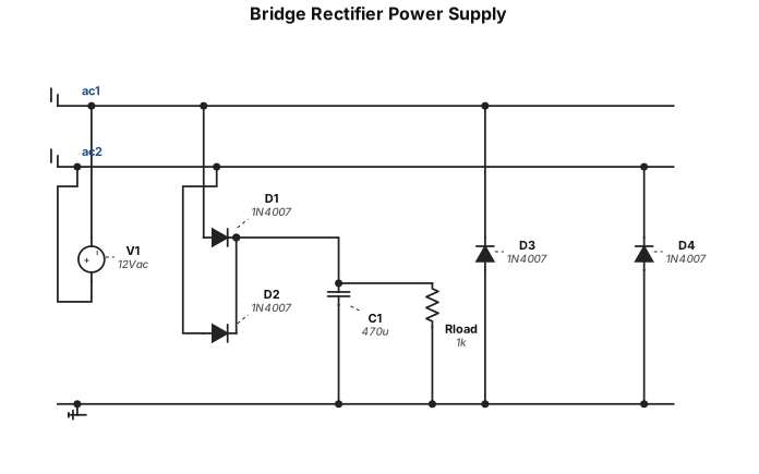
A bridge rectifier power supply with a 12 VAC source, four 1N4007 diodes, a 470 microfarad smoothing capacitor, and a 1 kilohm load.
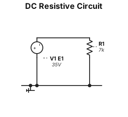
A DC resistive circuit includes a 35 V voltage source, 𝐸1, which supplies a current, 𝐼1, through 1 resistor, 𝑅1, which is 7 kΩ. The negative terminal of the voltage source is at ground.
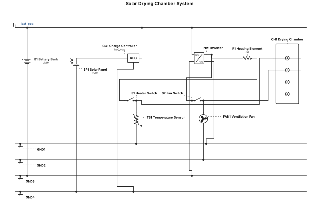
the system will use a solar panel, a charge controller, a inverter, battery, a heating element, a temperature sensor, a ventilation fan, and a drying chamber make a wiring diagram
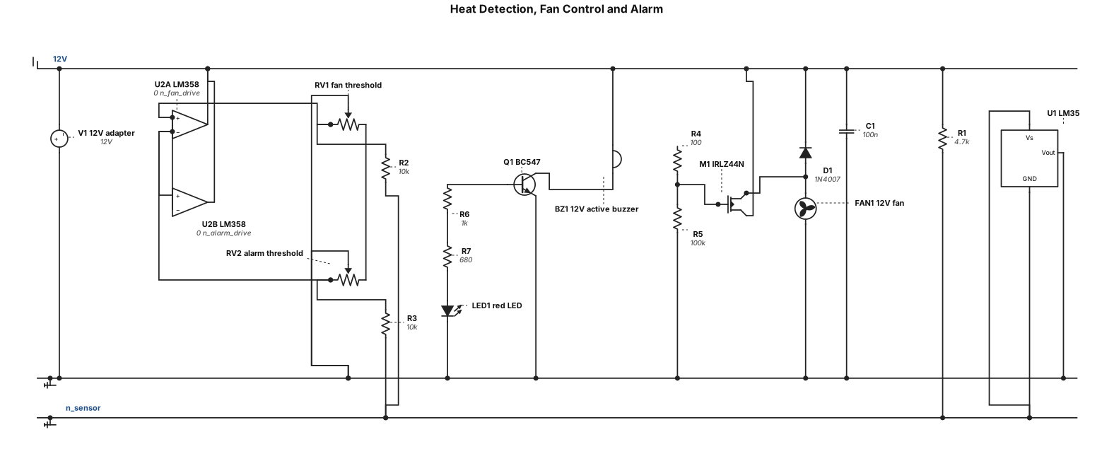
Design a detailed, beginner-friendly schematic for a low-voltage analog heat detection, automatic cooling fan, and high-temperature alarm project for an EEE college demonstration. Components available: LM35 temperature sensor (or TMP36 if the LM35 is unavailable), LM358P DIP-8 dual op-amp, two 10 kΩ PT10-2 potentiometers, IRLZ44N logic-level N-channel MOSFET, BC547 NPN transistor, 12 V DC fan, 12 V active buzzer, red LED, 1N4007 diode, resistors of 100 Ω, 1 kΩ, 4.7 kΩ, 100 kΩ and 680 kΩ, 100 nF capacitor, and a regulated 12 V adapter. Requirements: 1. Draw every component with reference designators and values. 2. Show exact pin numbers for the LM358, sensor, MOSFET, and BC547. 3. Label all power rails and grounds. 4. Include the fan flyback diode, LED current-limiting resistor, and safe buzzer driver. 5. Provide separate adjustable fan-on and alarm thresholds. 6. Check sensor voltage, comparator input range, MOSFET gate drive, resistor values, and output current limits. 7. Do not assume the design is correct merely because a schematic was generated. Identify uncertain connections and simulate or verify them before recommending construction. 8. Produce an editable schematic and a complete connection-by-connection wiring table. 9. If using TMP36, recalculate the threshold circuit for its voltage offset and specify its correct supply and pinout. Use low-voltage DC only; this is a demonstration project, not a certified fire alarm.
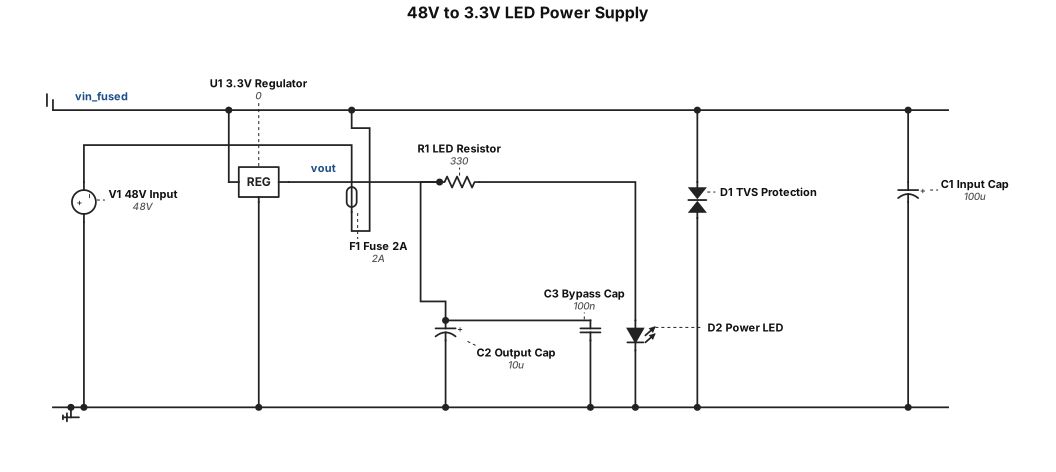
circuit converts 48v to 3,3 v and power to led with all the necessary circuit like the protection
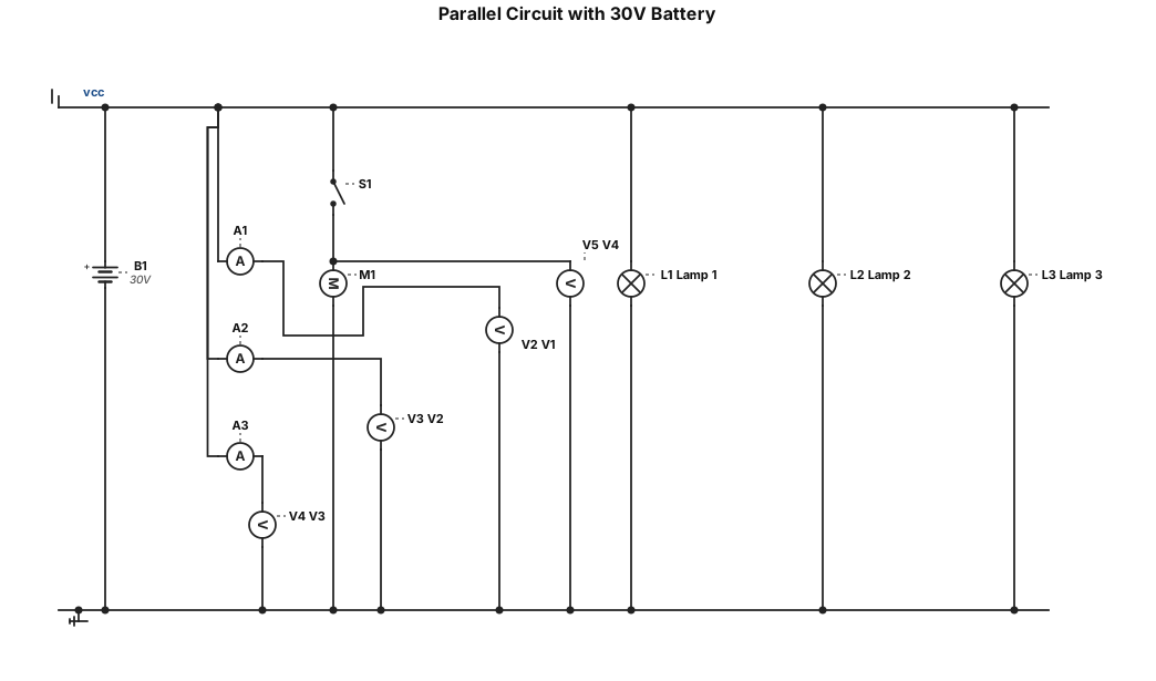
parallel ciruit diagram with 30V battery includes 3 lamps within ammeter and voltmeter in each lamp in which are first loop, the second loop includes motor and open switch and voltmeter includes in third branch
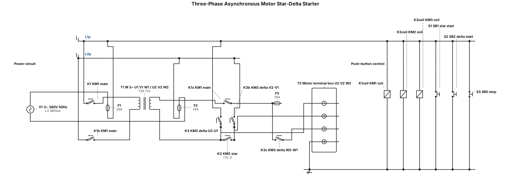
Draw and explain the operating principle of a circuit for starting a three-phase asynchronous motor using the star-delta (Y-Δ) connection method, controlled via push-buttons (one button for star-connection operation, one for delta-connection operation, and one for stopping the motor).