
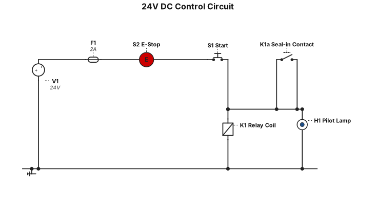
A 24 V DC control circuit with a fuse, emergency stop, start pushbutton, relay coil, seal-in contact, and one pilot lamp that turns on with the relay.
ENGINEERING DRAWING ARCHIVE · REAL SPECS
Engineering Diagram Examples from Real Specifications
Browse eligible circuit, ladder, single-line, P&ID, breadboard, timing, and logic drawings with their original prompts.
Browse 532 real creationsCOMMUNITY OUTPUTS · EXACT PROMPTS
Wiring Diagrams
Showing 1–17 of 17. No stock examples or system defaults. Choose a tool, study a real result, then reopen its prompt as your starting point.
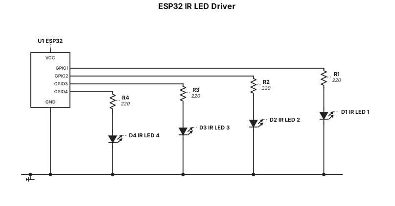
An ESP32 that connects 4 IR LEDs to output pins with a resistor in between, all connected through a breadboard
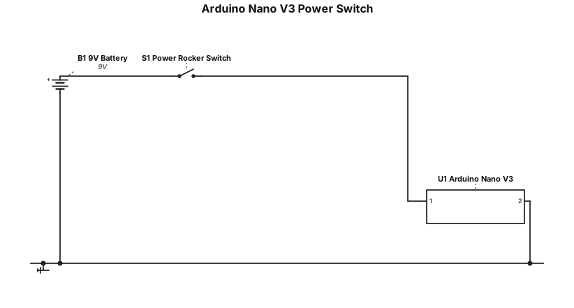
arduino nano v3, 9v battery gnd connected to arduino gnd, battery voltage connected to a power rocker switch, power rocker switch connected to vin on arduino
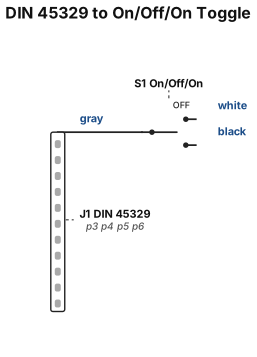
A circuit starting from a DIN 45329 connector. Pin 6 is attached via a white wire, pin 1 via a gray wire, pin 4 via a black wire. The wires terminate in 3-pin On/Off/On momentary toggle switch, white for center power signal, gray and black wires for the outer signal pins
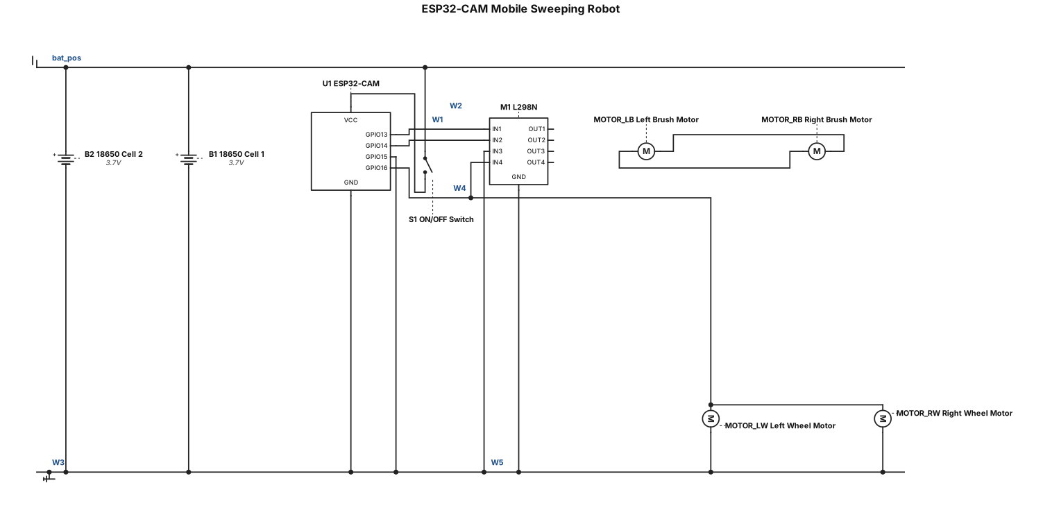
I want to build a MOBILE-CONTROLLED FLOOR SWEEPING ROBOT using ESP32-CAM without its camera module. Please design the complete project from scratch. I need the ACTUAL WIRING DIAGRAM with visible connections, not just code or a component layout. IMPORTANT: First create the circuit diagram, then generate the code. ## 1. COMPONENTS Use exactly these components: 1. One ESP32-CAM board without camera. 2. One L298N dual H-bridge motor driver. 3. Four TT shaft DC gear motors. 4. Two 18650 lithium-ion battery cells. 5. One ON/OFF switch. 6. Connecting wires. 7. A mobile phone for Wi-Fi control. Do not add a second motor driver. Do not add a vacuum cleaner motor. Do not add a camera. Do not add a boost converter or buck converter. ## 2. MOTOR CONNECTIONS — ONE L298N ONLY I have four TT DC gear motors. CHANNEL A — WHEELS: - Connect the left wheel motor across L298N OUT1 and OUT2. - Connect the right wheel motor in parallel across OUT1 and OUT2. - Both wheel motors must run together. CHANNEL B — ROTATING BRUSHES: - Connect the left brush motor across L298N OUT3 and OUT4. - Connect the right brush motor in parallel across OUT3 and OUT4. - Both brush motors must run together. Show all four motors individually in the wiring diagram, including every wire and parallel junction. Do not leave any motor disconnected. IMPORTANT: Check whether the combined current of each pair is safe for the L298N. If the motor current is unknown, clearly mark this as requiring verification. ## 3. ESP32-CAM CONTROL CONNECTIONS Use these proposed GPIO connections only if compatible with the selected ESP32-CAM board: - GPIO13 → L298N IN1 - GPIO14 → L298N IN2 - GPIO15 → L298N IN3 - GPIO16 → L298N IN4 - ESP32-CAM GND → L298N GND Verify GPIO availability and boot requirements for the exact ESP32-CAM variant. Keep EN
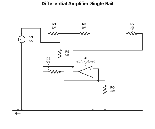
Differential amplifier with O.A. single rail +10V
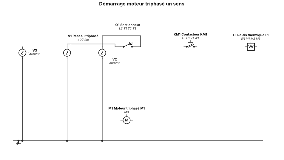
realise un motage moteur triphaser avec le sectionneur le contacteur et le relais thermique a un sens de marche
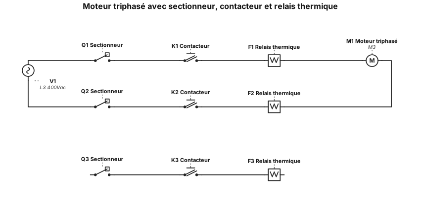
realise un motage moteur triphaser avec le sectionneur le contacteur et le relais thermique
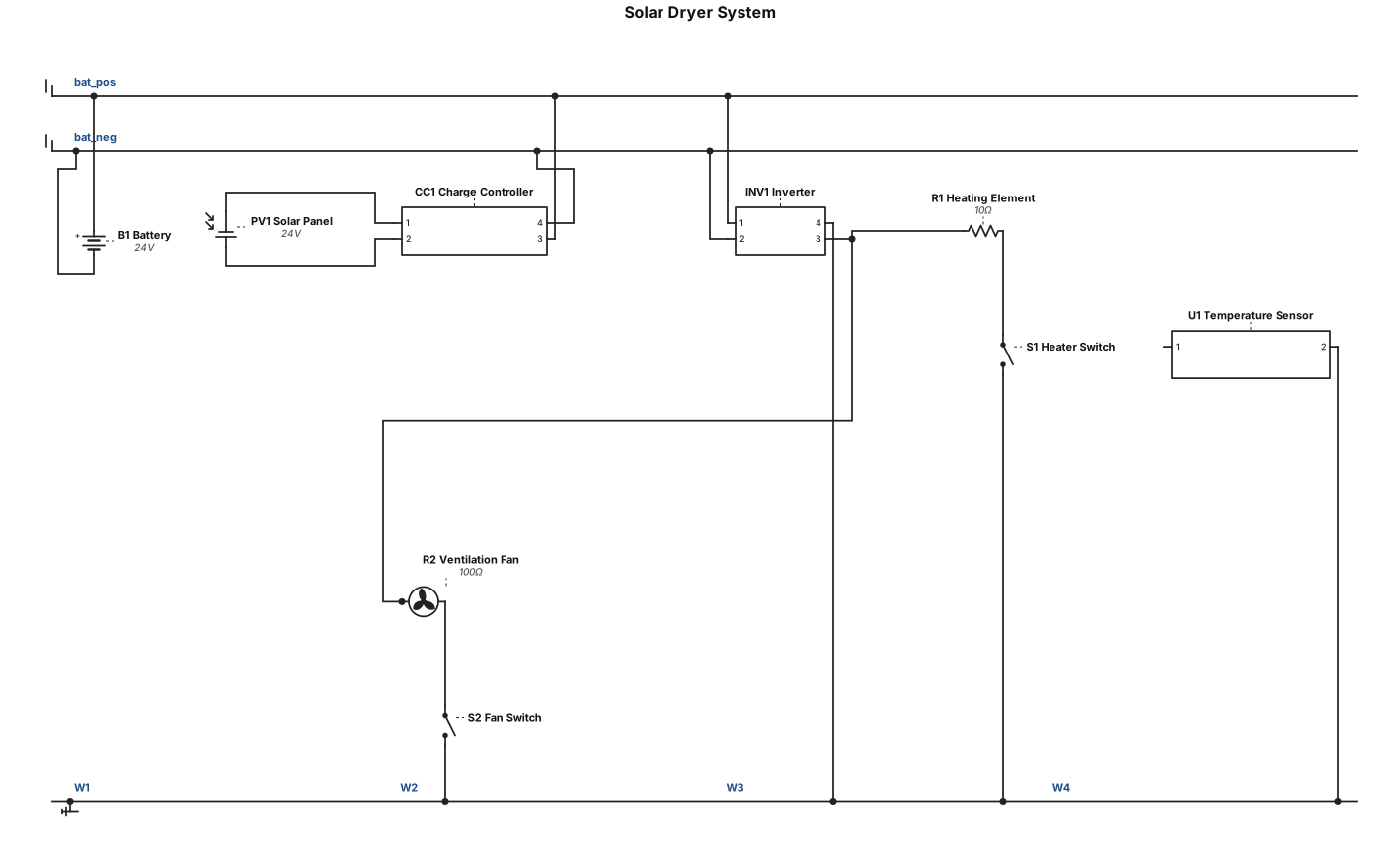
The system will use a solar panel, a charge controller, a inverter, battery, a heating element, a temperature sensor, a ventilation fan, and a drying chamber
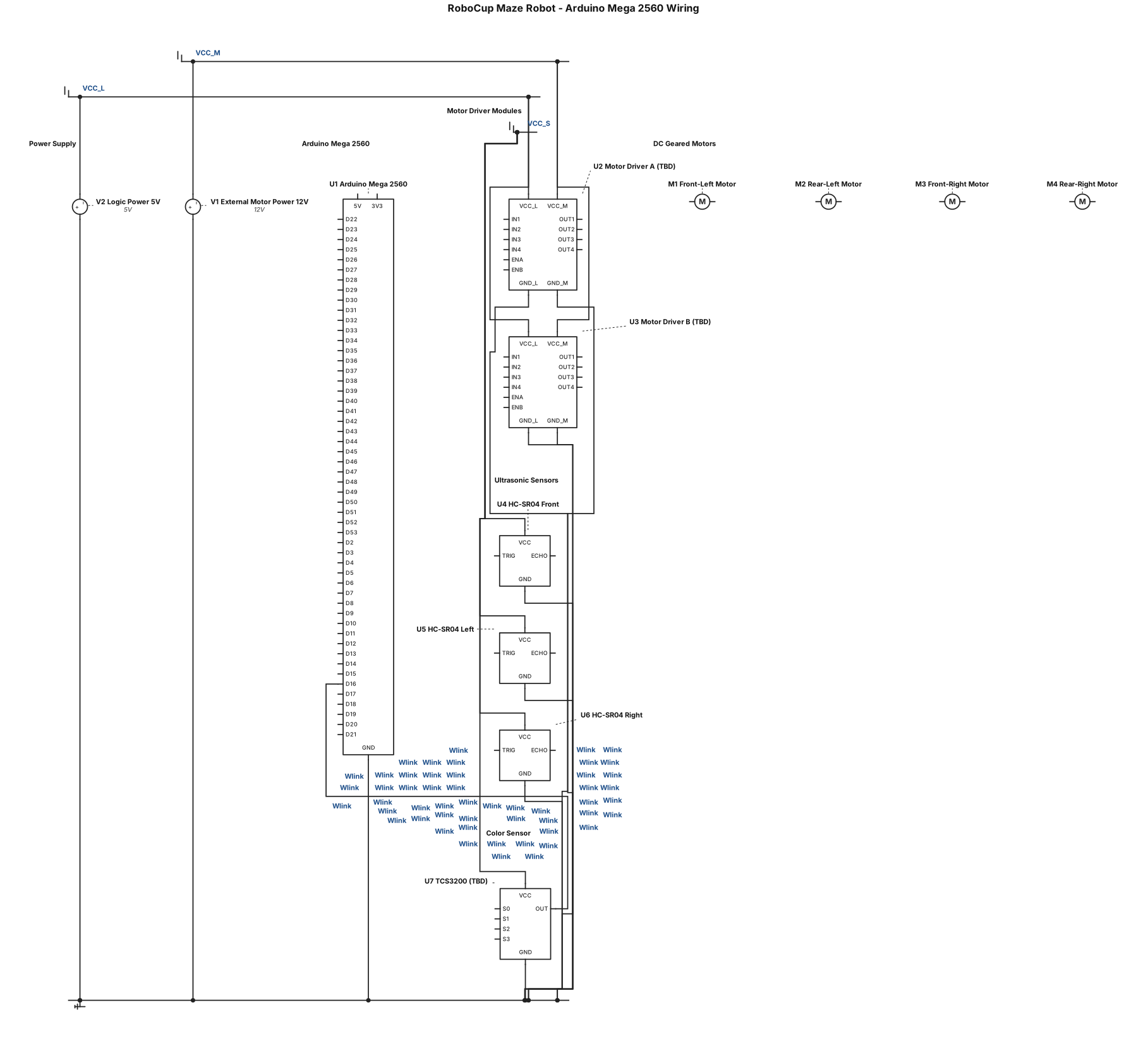
Create a detailed, neat, landscape-format electrical wiring diagram for a RoboCup maze-solving robot using an Arduino Mega 2560. COMPONENTS: 1. One Arduino Mega 2560. 2. Two dual-channel DC motor driver modules, each controlling two DC motors. 3. Four DC geared motors: front-left, rear-left, front-right, and rear-right. 4. Three HC-SR04 ultrasonic distance sensors: front, left, and right. 5. One TCS3200/TCS230 color sensor. DIAGRAM REQUIREMENTS: - Draw the actual Arduino Mega 2560 with its labeled digital pins, PWM pins, 5V, 3.3V, and GND. - Draw both motor driver modules with their control inputs, enable/PWM pins, motor outputs, logic power, motor power, and ground terminals. - Show all four motors connected to the correct motor driver outputs. - Draw each ultrasonic sensor with VCC, GND, TRIG, and ECHO pins. - Draw the TCS3200 color sensor with VCC, GND, S0, S1, S2, S3, and OUT pins. - Draw every wire separately and label BOTH ends of every connection with the exact pin names. - Use different colors for power, ground, motor control, and sensor signal wires. - Include a clear pin-to-pin connection table. - Show a suitable external motor power supply and common ground. - Do not power the motors directly from the Arduino 5V pin. - Avoid pin conflicts and account for PWM requirements. - Keep the diagram readable and suitable for printing as a PDF. IMPORTANT ACCURACY RULES: - Do not invent component models, pin connections, or electrical specifications. - The motor driver model has not yet been confirmed. Mark driver-specific connections as TBD until the exact model is known. - Use the TCS3200/TCS230 only as a provisional sensor choice; mark it TBD until confirmed. - Clearly identify any missing information. - Do not claim that the diagram has been electrically simulated or verified. OUTPUT: Generate a clear, professional, labeled wiring diagram and a pin-to-pin connection table for the Arduino Mega 2560 robot.
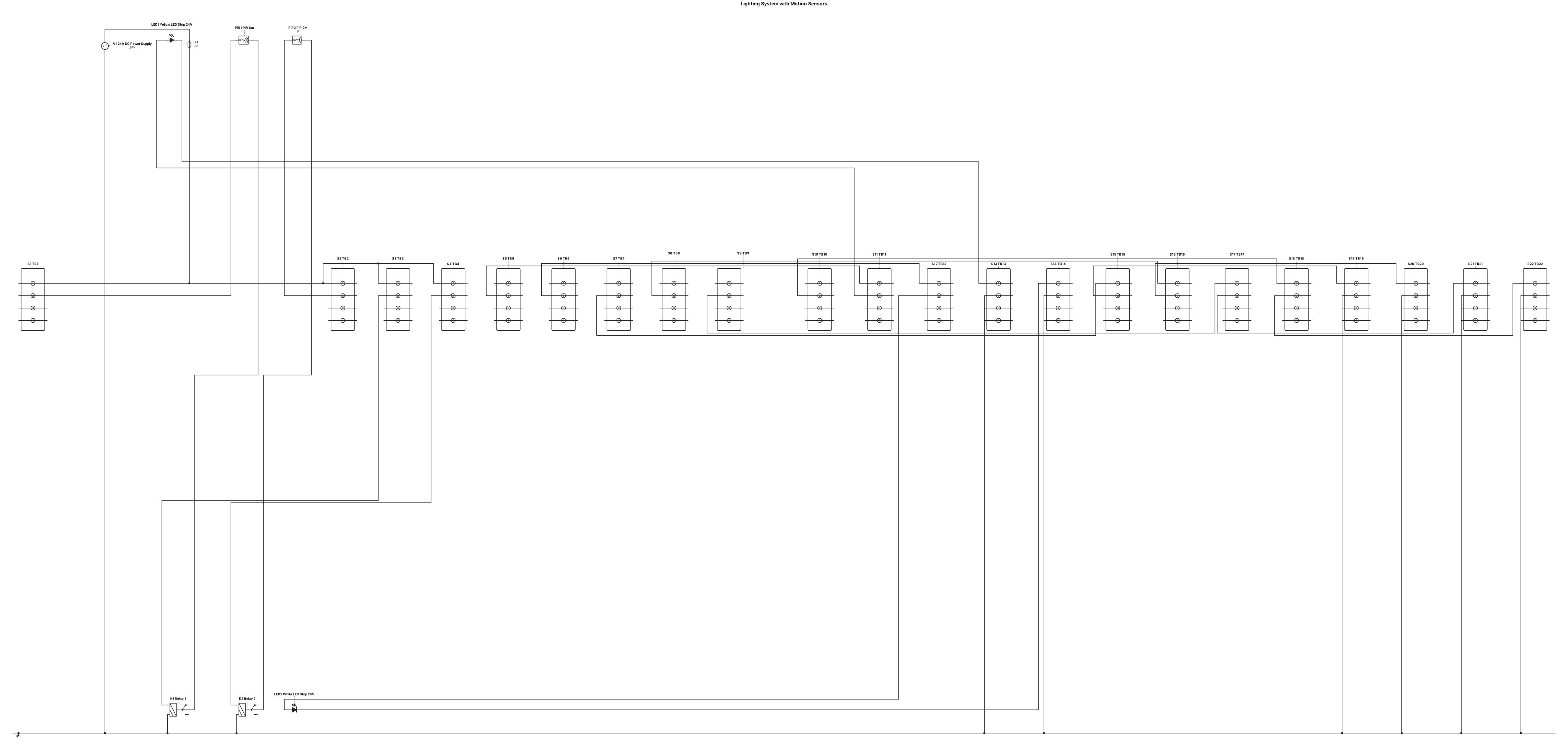
Design a wiring diagram for a lighting system. The components used are: 1× white LED strip, 24 V 1× yellow LED strip, 24 V 1× 24 V DC power supply 2× 24 V relays (COM, NO, NC) 1× PIR motion sensor with an 8 m detection range and a timer adjustable up to 7 minutes 1× motion sensor with a 2 m detection range and a timer adjustable up to 7 minutes You may use any number of terminal blocks, and an unlimited number of wires are available. The wiring system must operate as follows: The yellow LED strip must be activated when the motion sensor with an 8 m detection range is triggered. The white LED strip must be activated when the motion sensor with a 2 m detection range is triggered. Both motion sensors are installed in the same location. Both LED strips are installed in the same location. The two LED strips must never be illuminated simultaneously.
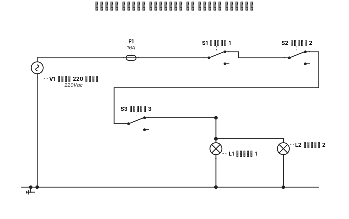
دائرة لتشغيل مصباحين من ثلاثة مفاتيح
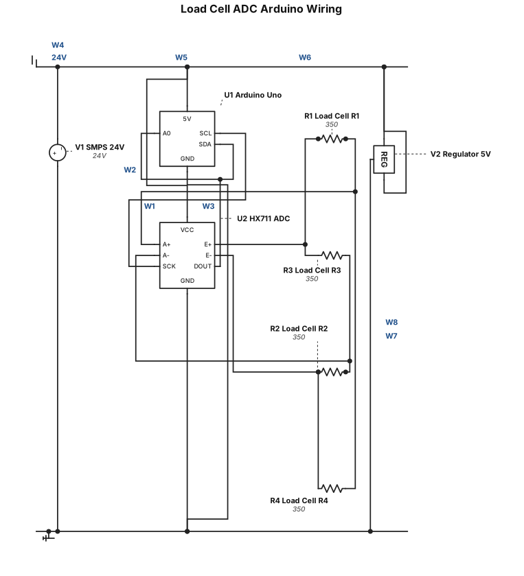
I am connecting loadcell with ADC and Arduino Uno. These will be powered from a SMPS. Created a professional electrical schematic wiring diagram between these components
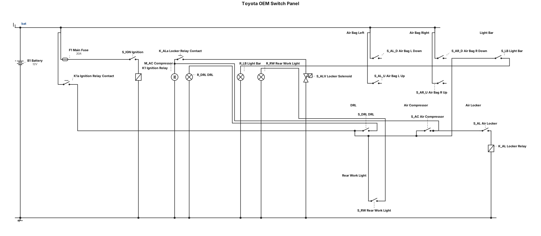
Create a clear circuit schematic with concise labels and the standard notation for this subject. Toyota oem switch 2 duel switchs for air bags left and right each switch up and down Then oem switchs for light bar drl air compressor air locker rear work light air locker not to work unless air compressor on air bags run constant power rest on ignition relay
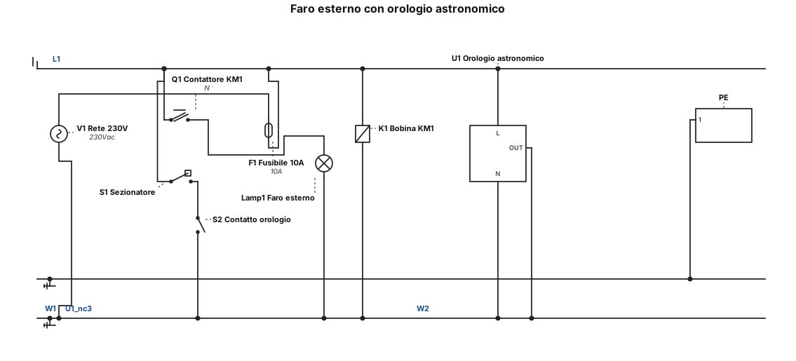
devo fare un circuito di potenza e di comando di un faro esterno comandato di notte da un orologio astronomico
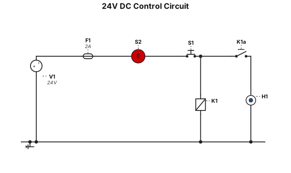
A 24 V DC control circuit with a fuse, emergency stop, start pushbutton, relay coil, seal-in contact, and one pilot lamp that turns on with the relay.
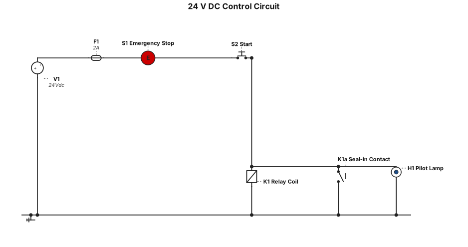
A 24 V DC control circuit with a fuse, emergency stop, start pushbutton, relay coil, seal-in contact, and one pilot lamp that turns on with the relay.