
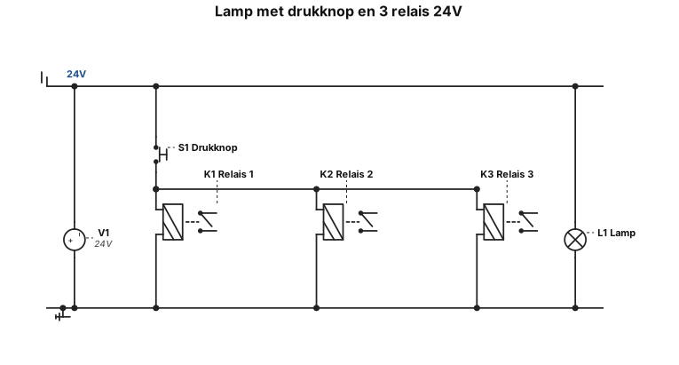
hoe een lamp met een drukknop en 3 reles bestuuren 24V
ENGINEERING DRAWING ARCHIVE · REAL SPECS
Engineering Diagram Examples from Real Specifications
Browse eligible circuit, ladder, single-line, P&ID, breadboard, timing, and logic drawings with their original prompts.
Browse 544 real creationsCOMMUNITY OUTPUTS · EXACT PROMPTS
Main engineering studio
Showing 217–240 of 380. No stock examples or system defaults. Choose a tool, study a real result, then reopen its prompt as your starting point.
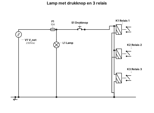
hoe een lamp met een drukknop en 3 reles bestuuren
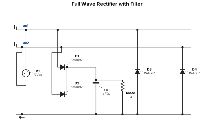
FULL WAVE RECTIFIER CIRCUIT WITH FILTER
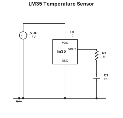
Use an LM35 temperature sensor. Connect pin 1 (VCC) to +5 V. Connect pin 3 (GND) to common ground. Connect pin 2 (VOUT) to a wire labelled VS. Connect VS to a 1 kΩ resistor in series. Connect the other end of the resistor to a node labelled VOUT. Connect a 10 µF capacitor between VOUT and common ground.
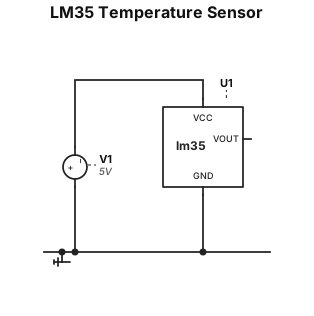
Use an LM35 temperature sensor. Connect pin 1 (VCC) to +5 V. Connect pin 3 (GND) to common ground. Connect pin 2 (VOUT) to a wire labelled VS.
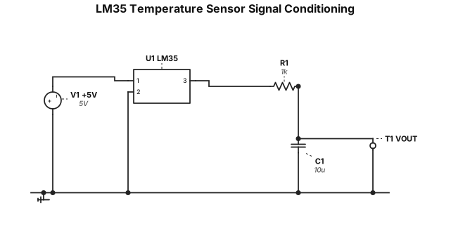
Create a simple and accurate electronic circuit schematic for a **Temperature Sensor Signal Conditioning Circuit without an op-amp**, suitable for a BTech ECE college project. **Block 1 – Temperature Sensor:** - Use an LM35 temperature sensor. - Connect its supply pin to +5 V. - Connect GND to common ground. - Label its output as VS. - If the LM35 model is unavailable, represent its output using a voltage source for simulation. **Block 2 – Signal Conditioning:** - Connect VS to a 1 kΩ resistor in series. - Connect a 10 µF capacitor from the resistor's output node to common ground. - Label the filtered output node VOUT. **Design requirements:** - No op-amp, transistor, or unnecessary components. - Use standard electronic circuit symbols. - Show all component values, supply voltage, ground connections, and output labels. - Make all electrical connections clear and correct. - Use a neat, simple schematic layout similar to LTspice. - Use a black background with clearly visible coloured wires. - Make the circuit easy to understand and explain during a college project exhibition. - Generate an actual circuit schematic, not a block diagram or a 3D illustration.
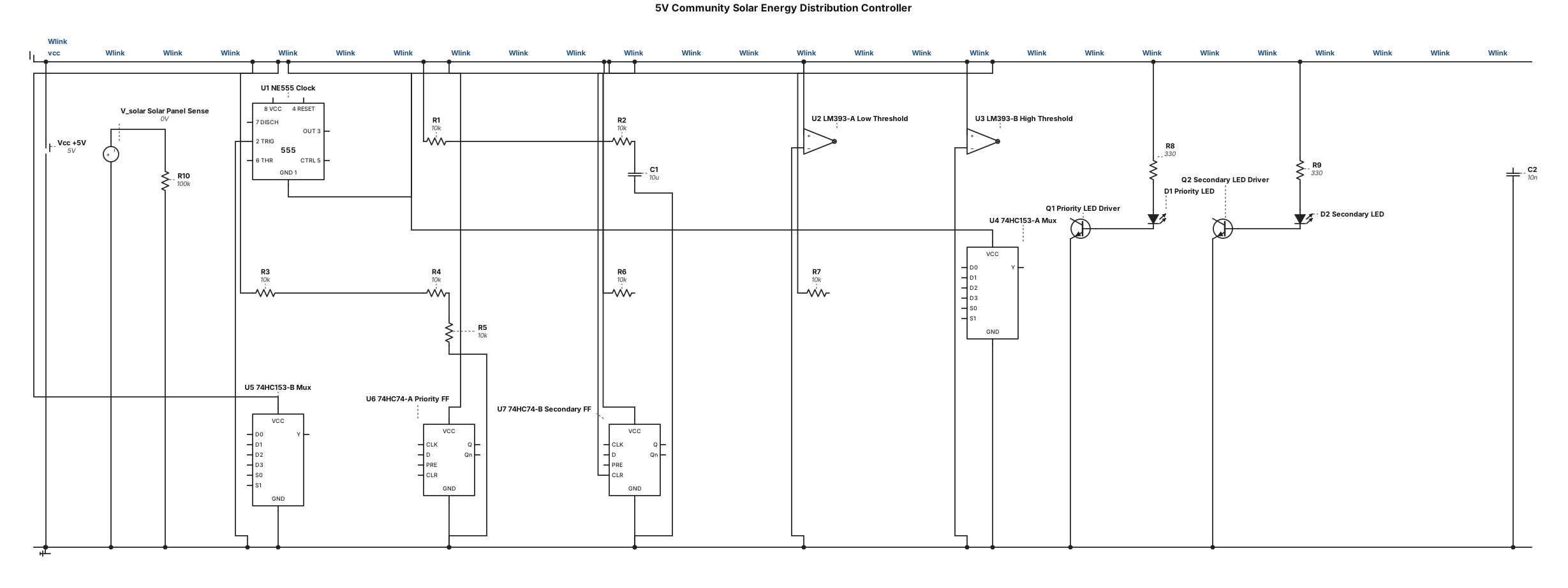
Design a 5 V community solar energy distribution controller using an LM393 dual comparator, 74HC74 D flip-flops, 74HC153 dual 4-to-1 multiplexer, and NE555 clock. Use two comparator thresholds to detect low, medium, and high power. At low power, both LED loads must be OFF. At medium power, only the priority LED must be ON. At high power, both LEDs must be ON. Show a complete, electrically correct schematic with exact IC pin numbers, pull-up resistors for LM393 outputs, common ground, and all power connections. Verify the pin connections before generating the diagram.
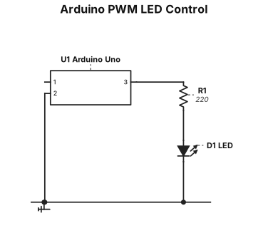
// C++ code // int i = 0; void setup() { pinMode(11, OUTPUT); } void loop() { for(i=0; i<=255; i+=10) { analogWrite(11,i); delay(300); // Wait for 1000 millisecond(s) analogWrite(11,0); delay(900); } }
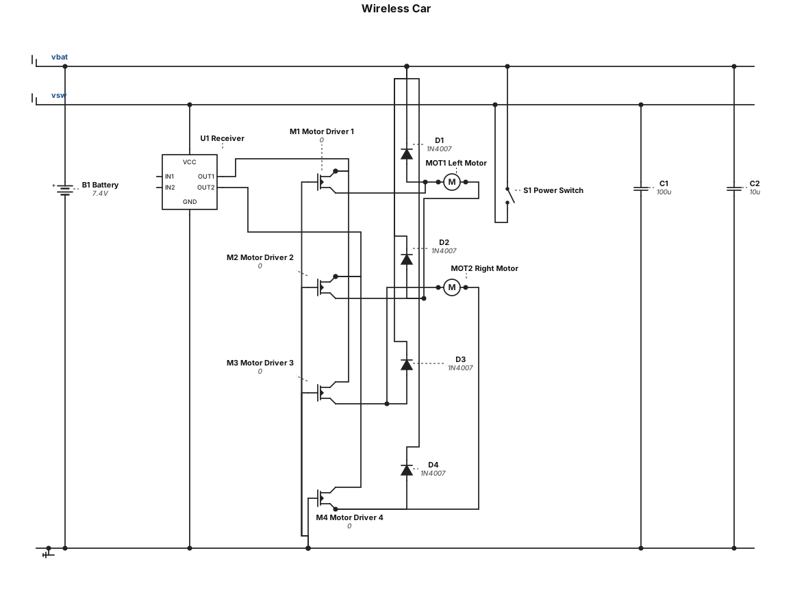
Wire less car
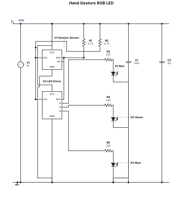
Hand gesture RGB led
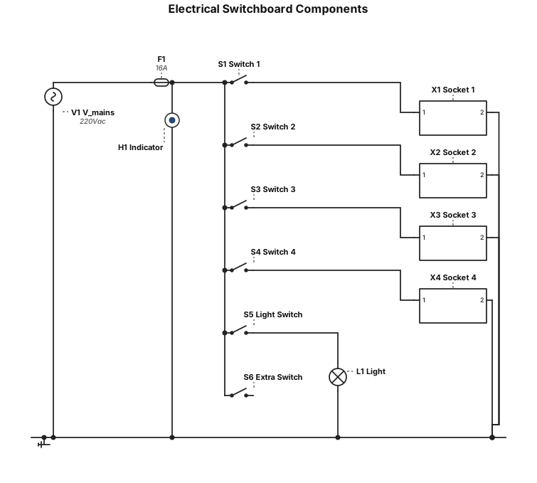
Electrical Switchboard Components: * 1 Indicator * 1 Fuse * 4 Switches * 4 Five-Pin Sockets * 1 Light Switch * 1 Extra Switch
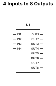
How make 4 inputs into 8 outputa
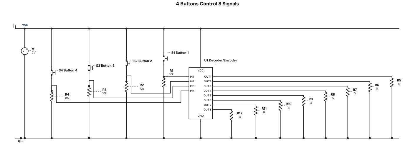
How make 4 physical buttons control 8 different signals
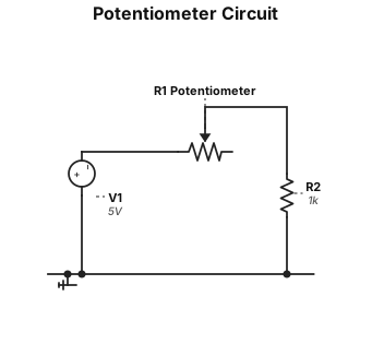
Create a circuit diagram with a potentiometer.
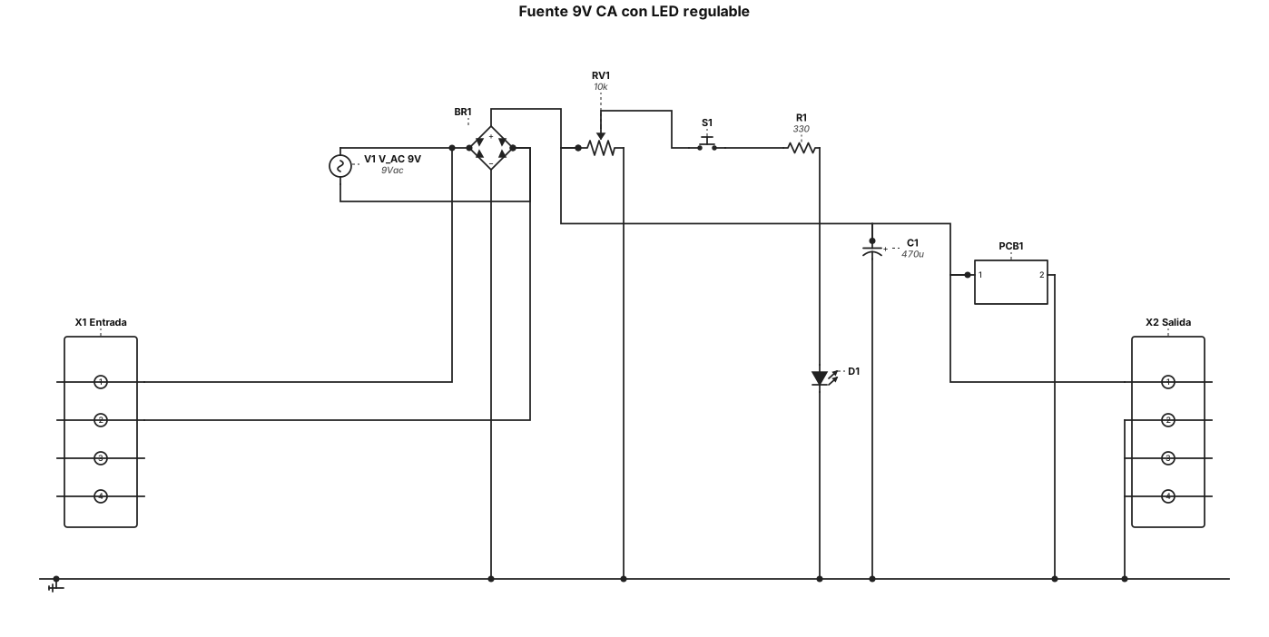
El circuito debe incluir los siguientes componentes identificados con referencias: C1: capacitor electrolítico. BR1: puente rectificador de cuatro diodos. RV1: potenciómetro. D1: LED indicador. R1: resistencia limitadora para el LED. X1 y X2: borneras de entrada y salida. S1: pulsador normalmente abierto. PCB1: placa de circuito impreso como soporte físico. Utilizá una alimentación aislada de baja tensión, de 9 V CA, seguida por el puente rectificador y el capacitor de filtrado. Incorporá un circuito indicador con LED, resistencia, pulsador y potenciómetro para regular el brillo. Mostrá claramente todas las conexiones, la polaridad del capacitor y del LED, los terminales del potenciómetro y las referencias de cada componente.
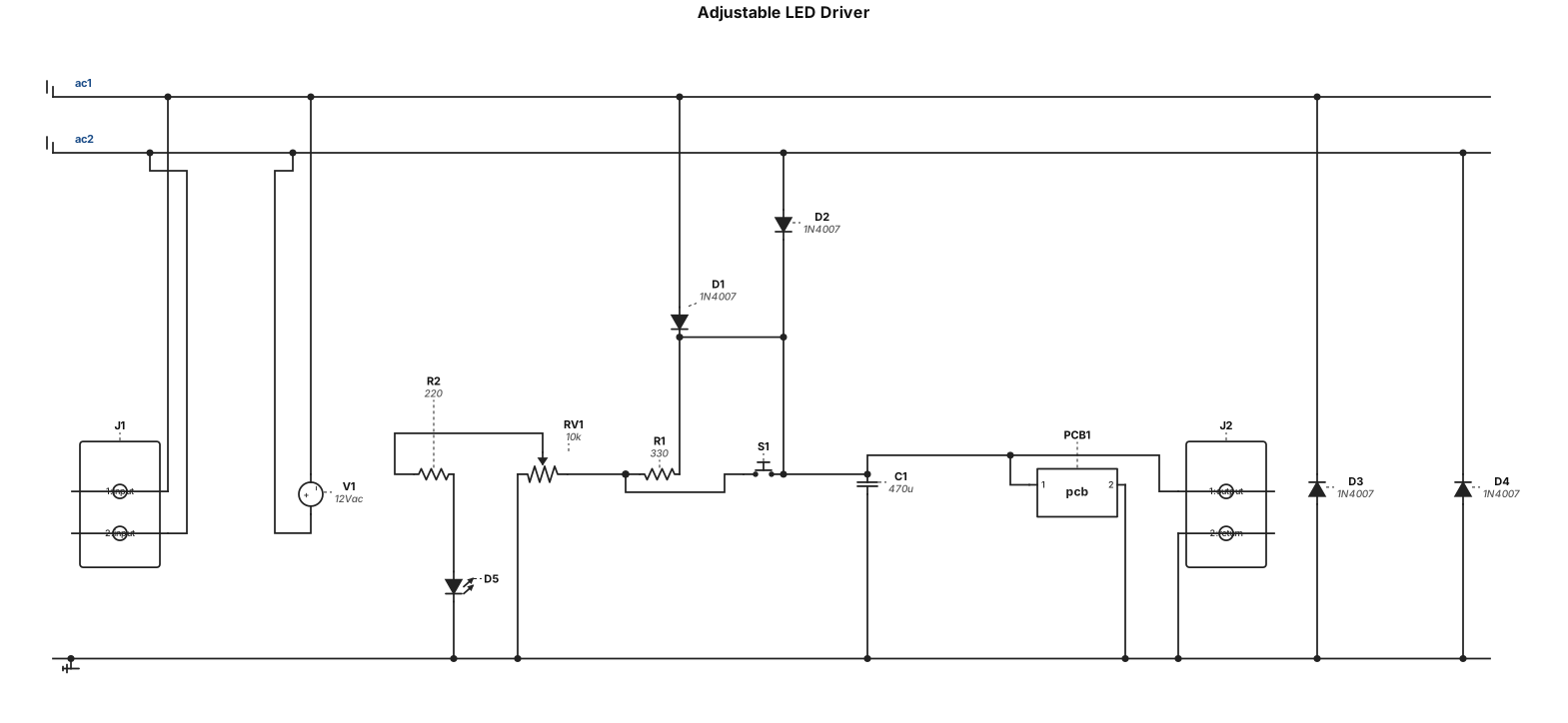
Design a circuit that includes a capacitor, a diode bridge, a potentiometer, an LED and a resistor, a PCB, terminal blocks, solder, and a push button. You can choose the component values as you prefer; just try to make the circuit functional and practical to use.
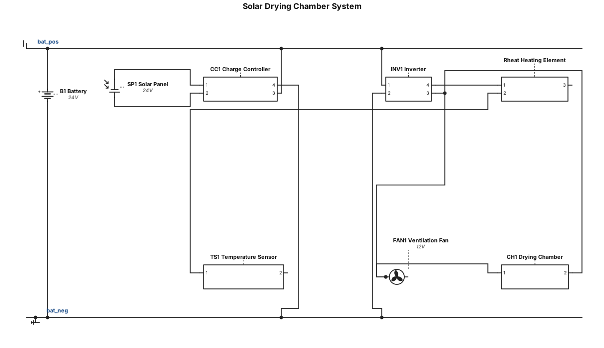
solar panel, a charge controller, a inverter, battery, a heating element, a temperature sensor, a ventilation fan, and a drying chamber
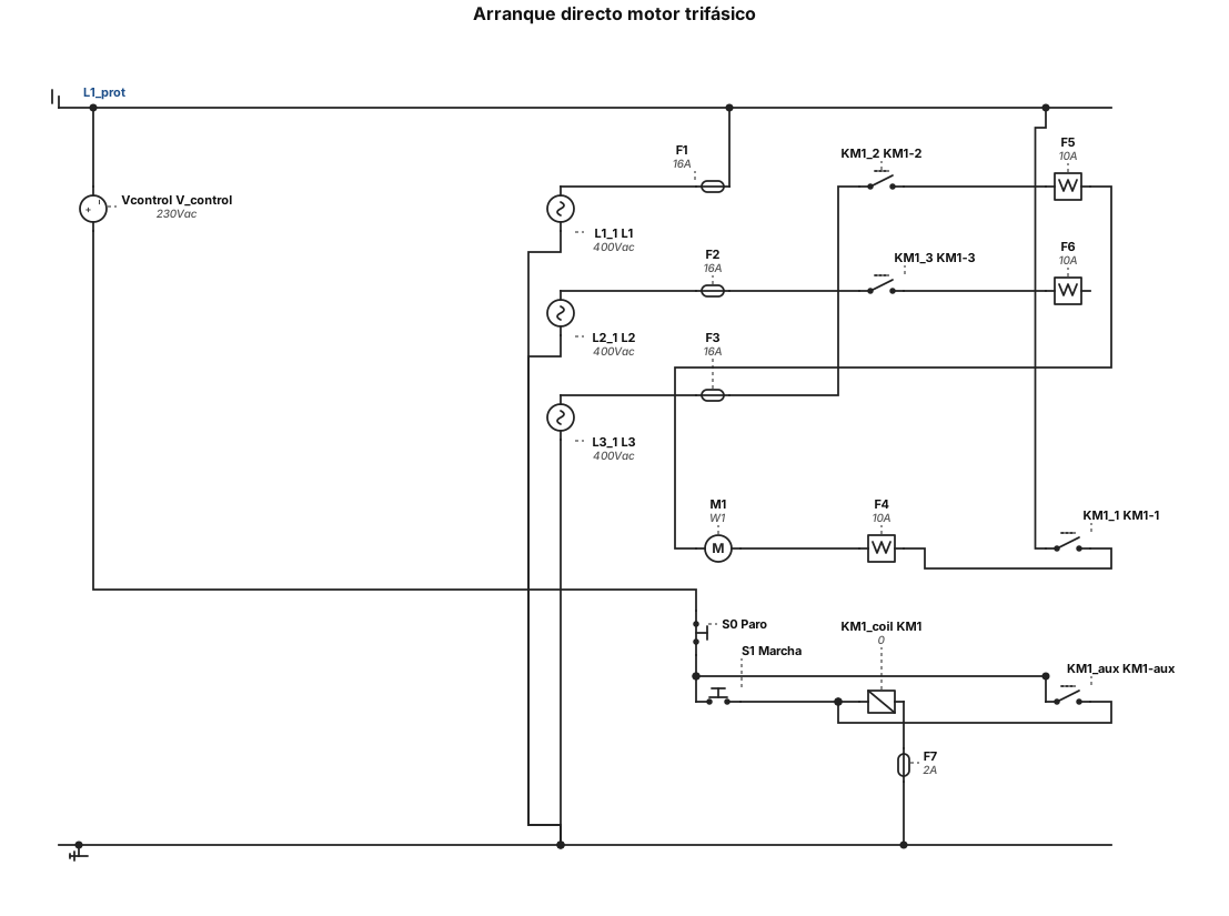
Diseña un circuito de arranque directo para un motor trifásico. Incluye el circuito de potencia y el circuito de mando, con contactor, relé térmico, pulsador de marcha y pulsador de paro. Identifica todos los componentes y muestra claramente las conexiones eléctricas.
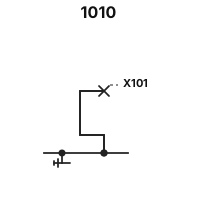
1010 X101
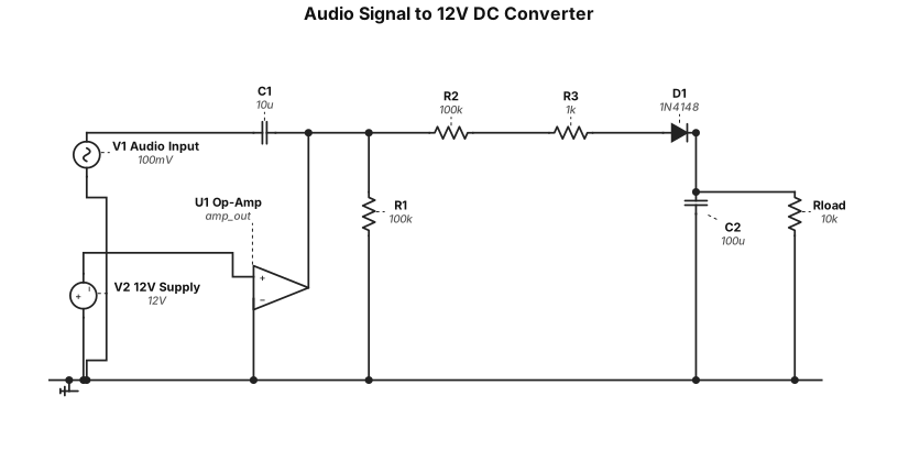
convert a 100mV audio signal to 12 Volt DC
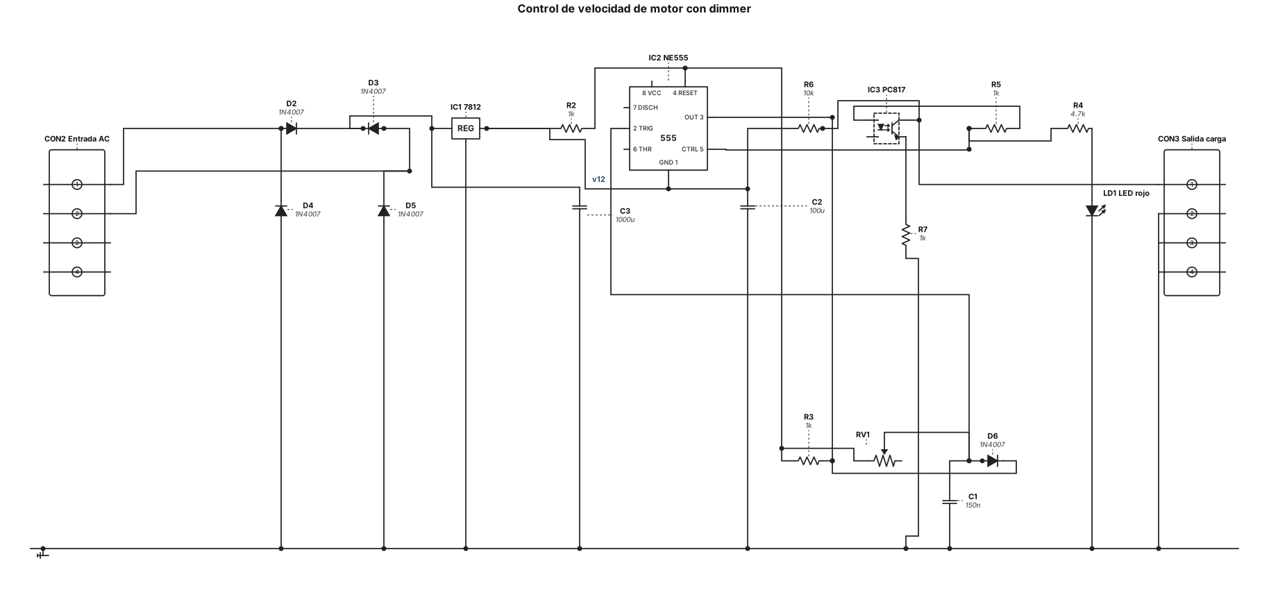
Quiero recrear y analizar en CircuitMaker un circuito de control de velocidad de un motor con dimmer, siguiendo el esquema adjunto. Componentes: IC1: regulador de tensión 7812. IC2: temporizador NE555. IC3: optoacoplador PC817. D2, D3, D4, D5 y D6: diodos 1N4007. LD1: LED rojo. R2: 1 kΩ. R3: 1 kΩ. R4: 4,7 kΩ. R5: 1 kΩ. R6: 10 kΩ. R7: 1 kΩ. RV1: potenciómetro de 50 kΩ. C1: 150 nF. C2: 100 µF. C3: 1000 µF. CON2: conector de dos pines para entrada AC del transformador. CON3: conector de dos pines para salida hacia la carga. Fuente de alimentación regulada de 12 V CC para el circuito de control. Tierra GND. Usa las conexiones del esquema adjunto, sin inventar conexiones que no se puedan identificar. Comprueba las conexiones del NE555 y del PC817 antes de ejecutar la simulación. Necesito obtener gráficas de: Tensión alterna de entrada AC1-AC2. Tensión de alimentación de 12 V. Tensión en el condensador C1 y en el pin 2 (TRIG) del NE555. Tensión en el pin 3 (OUT) del NE555: señal cuadrada o PWM. Variación del ciclo de trabajo al mover el potenciómetro RV1. Señal de salida de la etapa de potencia hacia el motor, solo si el esquema completo incluye el dispositivo de conmutación necesario. Genera las formas de onda con ejes de tensión y tiempo, indicando los puntos de medición y los valores utilizados en la simulación. Si algún componente o conexión no está definido, indícalo antes de completar el circuito.. Qué formas de onda deberías obtener - Entrada AC: una onda senoidal. - Alimentación del 7812: una tensión continua cercana a 12 V. - Salida del NE555, pin 3: una señal de pulsos; su forma exacta depende de la configuración real del circuito. - Salida hacia el motor: depende de la etapa de potencia y de si el esquema incluye el dispositivo de conmutación correspondiente.
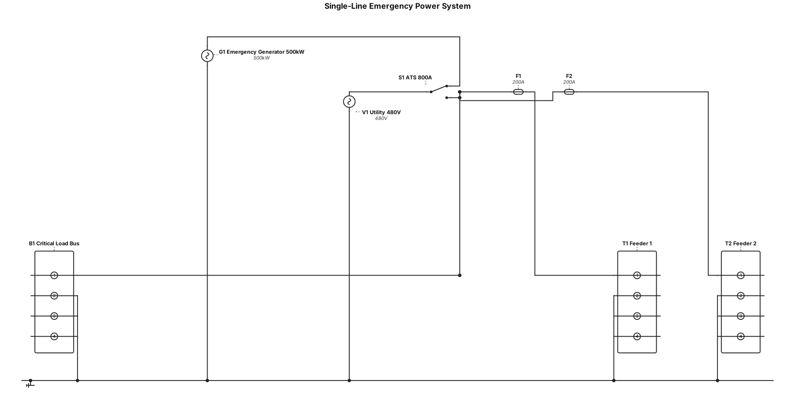
A single-line diagram with a 480 V utility, a 500 kW emergency generator, an 800 A automatic transfer switch, a critical-load bus, and two 200 A feeders.
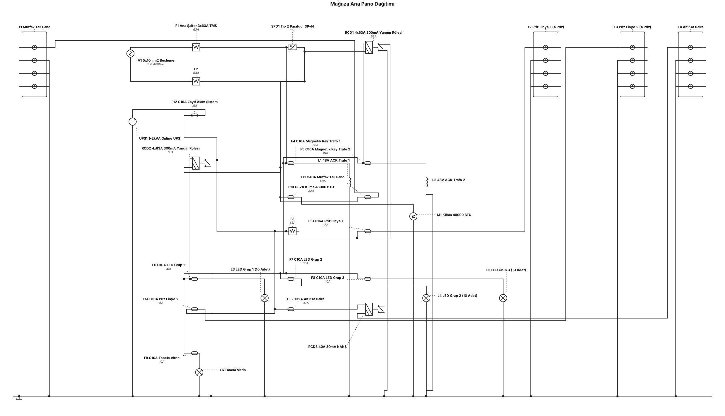
Ana panoya giren $5 \times 10\text{ mm}^2$ beslemeyi 3 faza ($R, S, T$) dengeli dağıtmak panonun ısınmasını ve şalter atmasını engeller.Giriş ve Genel Koruma Ekipmanları (Pano Girişi):Ana Şalter: $1 \times 3\times63\text{A}$ Termik Manyetik Şalter (TMŞ) veya Yük Kesici.Aşırı Gerilim Koruyucu (Parafudr): $1 \times \text{Tip 2 (C Sınıfı) 3P+N}$ Parafudr (Hassas kamera, kayıt cihazı ve LED trafolarını yıldırım/şebeke darbesinden korur).Ana Kaçak Akım Koruma: $1 \times 4\times63\text{A } 300\text{mA}$ Yangın Koruma Rölesi (Veya linyeler bazında $30\text{mA}$ KAKŞ grupları).Faz Dağılım Planı:R FAZI (Aydınlatma ve Vitrin Ağırlıklı)48V ACK Magnetik Ray Trafoları: $2 \times \text{C16A}$ Sigorta.Mağaza Genel LED / Spot Aydınlatma (30 Adet): $3 \times \text{C10A}$ Sigorta (Aydınlatmalar 3 ayrı gruba/linyeye bölünmelidir).Tabela & Vitrin Aydınlatma: $1 \times \text{C10A}$ Sigorta (Astronomik zaman rölesi veya akıllı röle üzerinden).S FAZI (İklimlendirme ve Mutfak Tali Pano Beslemesi)48.000 BTU Klima Linyesi: $1 \times \text{C32A}$ Sigorta ($3 \times 6\text{ mm}^2$ Kablo ile direkt klimaya).Mutfak Tali Pano Besleme Hattı: $1 \times \text{C40A}$ Sigorta ($3 \times 6\text{ mm}^2$ Kablo ile mutfak panosuna).T FAZI (Zayıf Akım, Prizler ve Alt Kat Daire)Zayıf Akım ve Sistem Grubu (Kabinet / Rack): $1 \times \text{C16A}$ Sigorta.Bu hat arkasına $1-2\text{ kVA}$ Online UPS (KGK) konulmalıdır. NVR Kayıt cihazı, 11 adet IP Kamera PoE Switch'i, Modem ve Ses Amfisi doğrudan UPS'ten beslenmelidir.Mağaza İçi Priz Linyeleri (8 Adet Priz): $2 \times \text{C16A}$ Sigorta ($3 \times 2.5\text{ mm}^2$ Kablo).Alt Kat Daire Besleme Hattı: $1 \times \text{C32A}$ veya $\text{C40A}$ Sigorta + $1 \times 40\text{A } 30\text{mA}$ KAKŞ
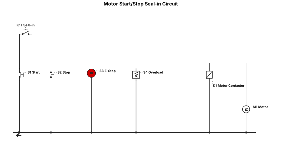
A PLC ladder diagram for a motor start/stop seal-in circuit with an emergency-stop interlock and an overload contact.