
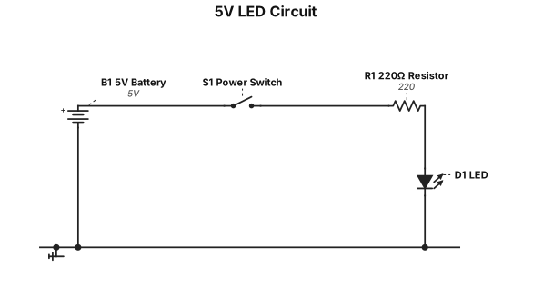
Create a simple 5V LED circuit with a 220-ohm resistor, switch, battery, and clear component labels.
ENGINEERING DRAWING ARCHIVE · REAL SPECS
Engineering Diagram Examples from Real Specifications
Browse eligible circuit, ladder, single-line, P&ID, breadboard, timing, and logic drawings with their original prompts.
Browse 548 real creationsCOMMUNITY OUTPUTS · EXACT PROMPTS
Main engineering studio
Showing 265–288 of 381. No stock examples or system defaults. Choose a tool, study a real result, then reopen its prompt as your starting point.
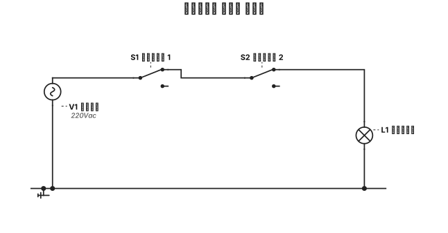
رسم دائره وسط سلم
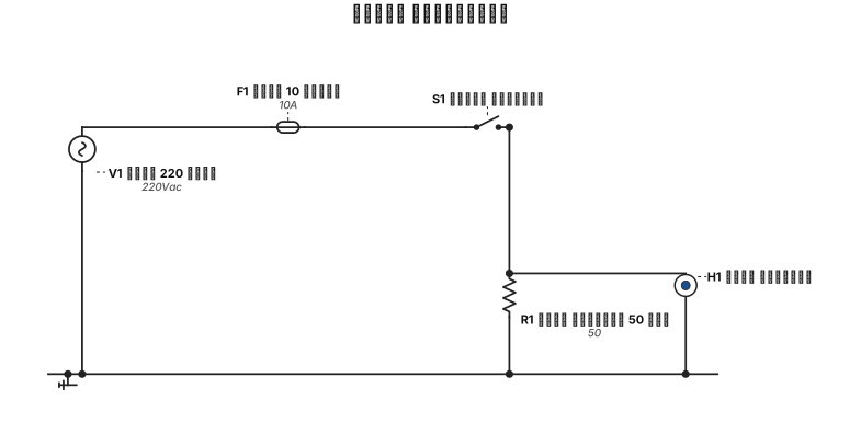
رسم دائره الدفياتير
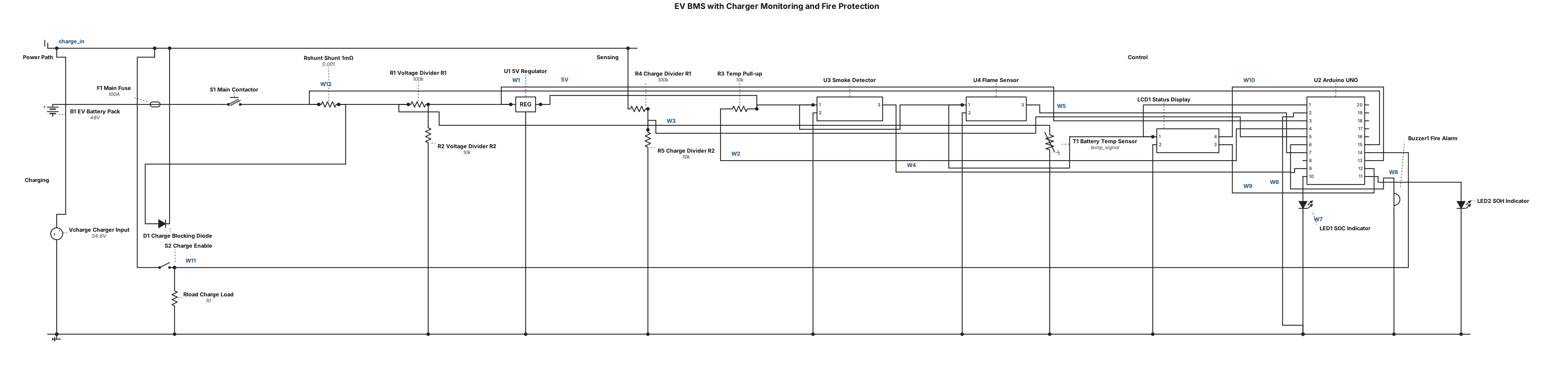
EV BMS with Charger Monitoring and Fire Protection along with SOC,SOH using Arduino UNO.
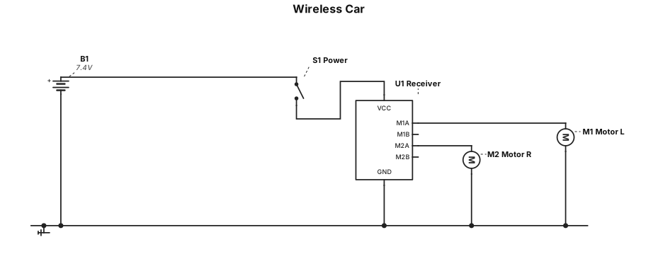
wire less car
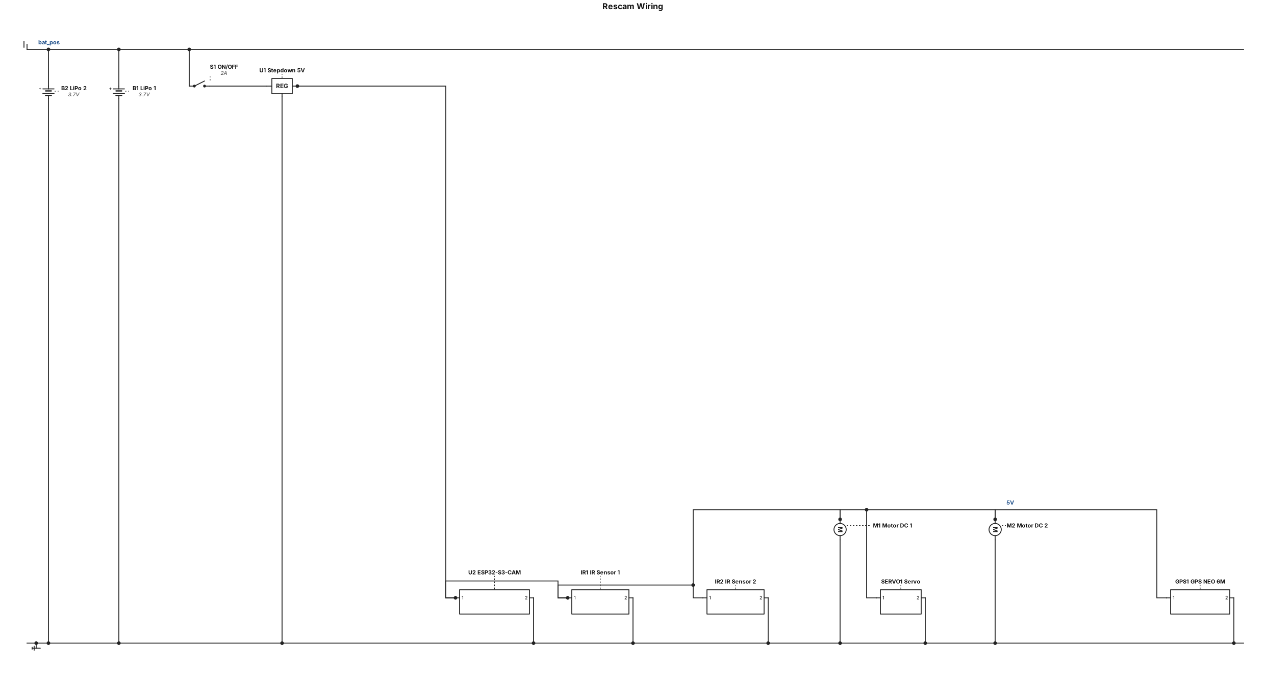
buatkan wiring untuk project ku yang bernama rescam komponennya ada: ESP32-S3-CAM, IR SENSOR 2x, Baterai LiPo 2x, servo, morot DC 2x, GPS NEO 6M, ON/OFF SWITCH, stepdown 5v
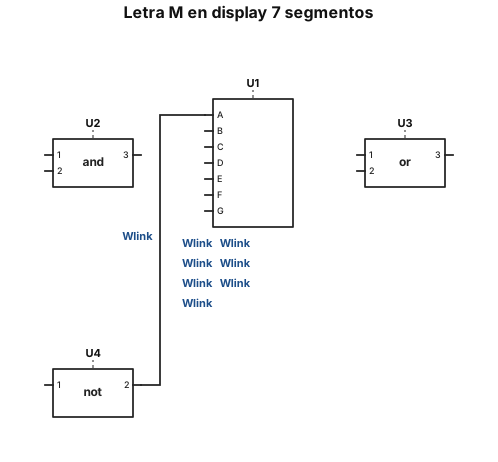
necesito que con la compuestas logicas and,not,or junto un display de 7 segmentos hagan la letra m con a,f,g,e,d
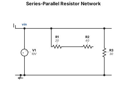
a 10V source drives a 20Ω and 40Ω resistor in series, parallel with a 30Ω resistor. find rt
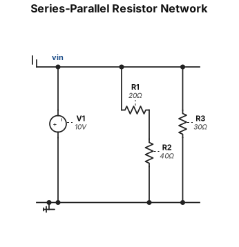
a 10V source drives a 20Ω and 40Ω resistor in series, parallel with a 30Ω resistor
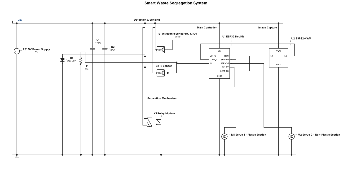
Hi, I am working on a Smart Waste Segregation Project. My Project Idea The main aim of my project is to automatically identify plastic and non-plastic waste and separate them into different sections. Components I Have - ESP32 DevKit – main controller - ESP32-CAM – captures the image of the waste - Ultrasonic sensor – detects the object/distance - IR sensor – detects the presence of an object - 2 Servo motors – moves the waste to the correct section - Relay module - Breadboard - Jumper wires - 5V power supply How I Want It to Work 1. A waste item is placed into the system. 2. The ultrasonic/IR sensor detects the object. 3. The ESP32-CAM captures its image. 4. The system identifies whether it is plastic or non-plastic. 5. The ESP32 receives the result. 6. Based on the result, the servo motor moves the waste to the correct section. 7. Then the system is ready for the next item. Important Requirement If multiple plastic and non-plastic items are put together, I want the system to process them one by one, so that the camera can identify each item properly. I need help with the complete circuit connection, ESP32 + ESP32-CAM communication, image classification method, coding, and the mechanical separation mechanism. My final goal is to make a proper working model where: Waste detected → Image captured → Plastic/Non-Plastic identified → Automatically separated.
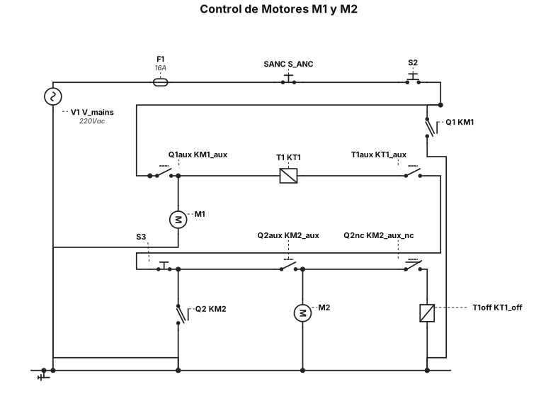
S2 NO produce la mancha de M1. lo segundos después arranca M2. SANC solo detiene a M1 S3 NC solo detiene a M2 Proteger con guandamotores PISTAS → redimentar a Q2 pmotor 2 1 Cando arange M2 descondó al temporizador → usar contactos aukliares.
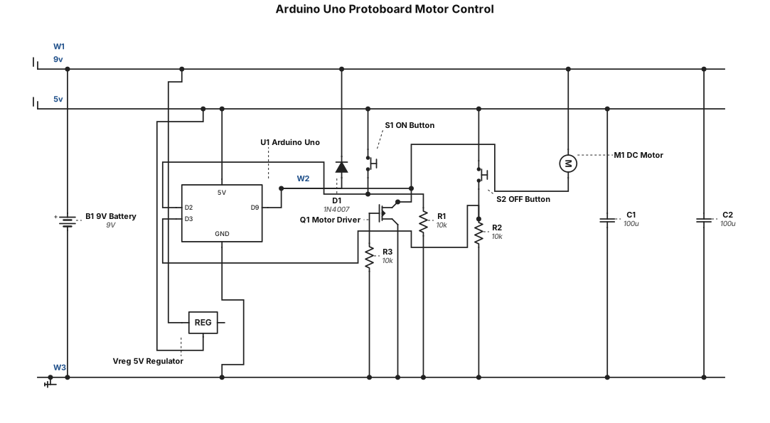
generate it in a protoboard for arduino one and a protoboard basic, give me a circuit with 2 push buttoms that control a motor, one of them for turning it on, and other for turning off, and a 9v baterry powering que motor
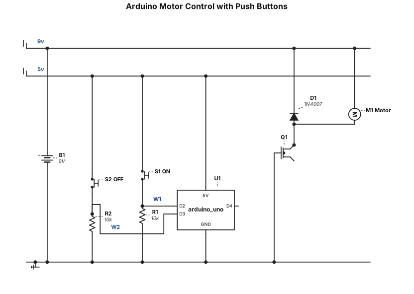
for arduino one and a protoboard basic, give me a circuit with 2 push buttoms that control a motor, one of them for turning it on, and other for turning off, and a 9v baterry powering que motor
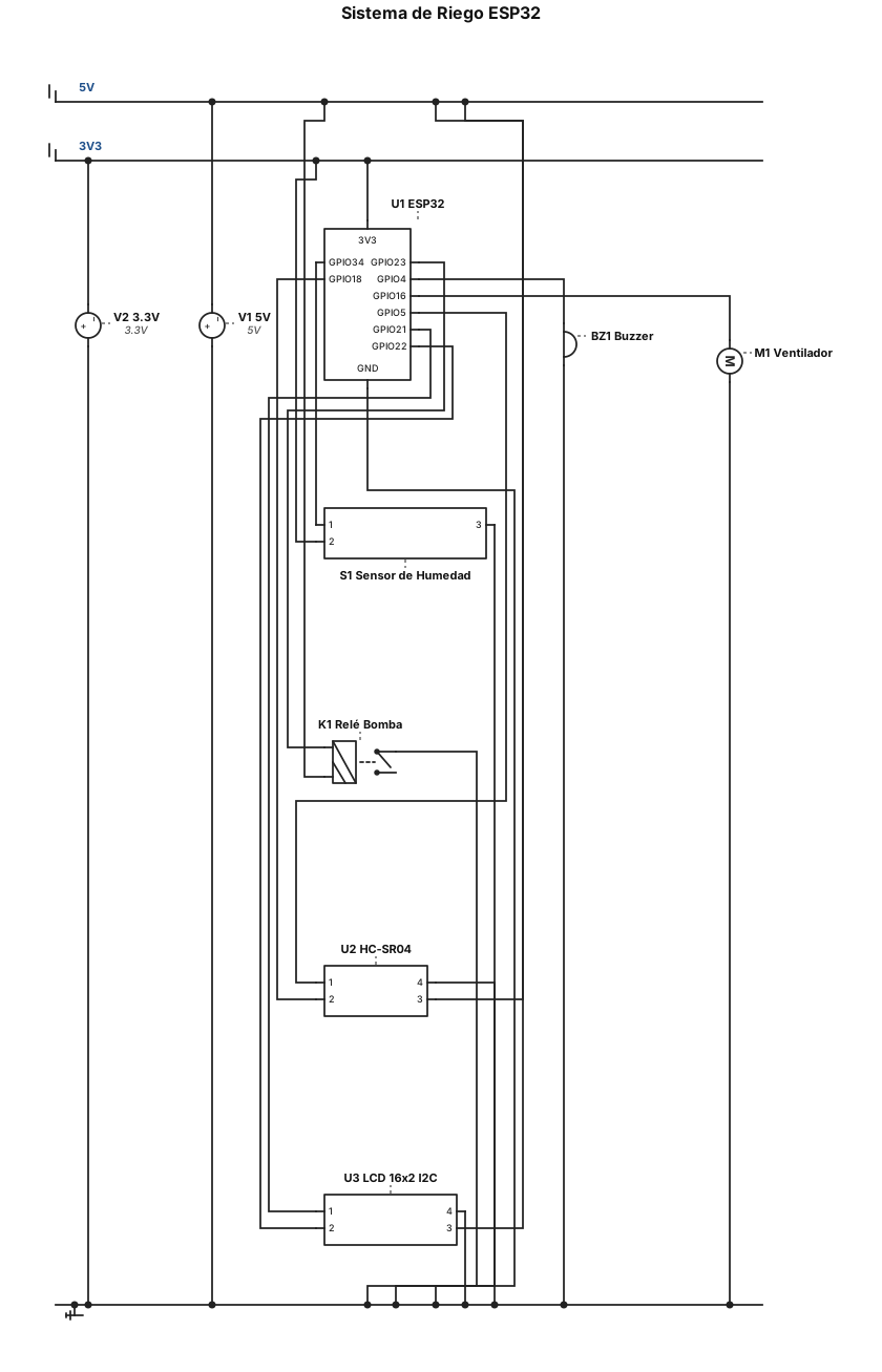
### 1. Sensores y Actuadores Principales - **Sensor de Humedad del Suelo (Analógico):** - Pin de señal (AO) $\rightarrow$ **Pin 34** de la ESP32 - VCC $\rightarrow$ 3.3V o 5V (según tu módulo) - GND $\rightarrow$ GND - **Módulo de Relé (Bomba de Agua):** - Pin de control (IN) $\rightarrow$ **Pin 23** - VCC $\rightarrow$ 5V - GND $\rightarrow$ GND - **Buzzer (Alarma):** - Pin positivo (+) $\rightarrow$ **Pin 4** - Pin negativo (-) $\rightarrow$ GND - **Ventilador (vía Driver L293D / Transistor):** - Pin de control de velocidad/activación (IN1) $\rightarrow$ **Pin 16** ### 2. Sensor Ultrasónico (HC-SR04 - Nivel de Agua) - **Trig:** Conectado al **Pin 5** - **Echo:** Conectado al **Pin 18** *(Nota: El pin Echo trabaja a 5V, idealmente usa un divisor de tensión con resistencias si quieres proteger la ESP32, aunque muchos módulos funcionan directo)* - **VCC:** 5V - **GND:** GND ### 3. Pantalla LCD 16x2 con Adaptador I2C - **SDA:** Conectado al **Pin 21** de la ESP32 - **SCL:** Conectado al **Pin 22** de la ESP32 - **VCC:** 5V - **GND:** GND .
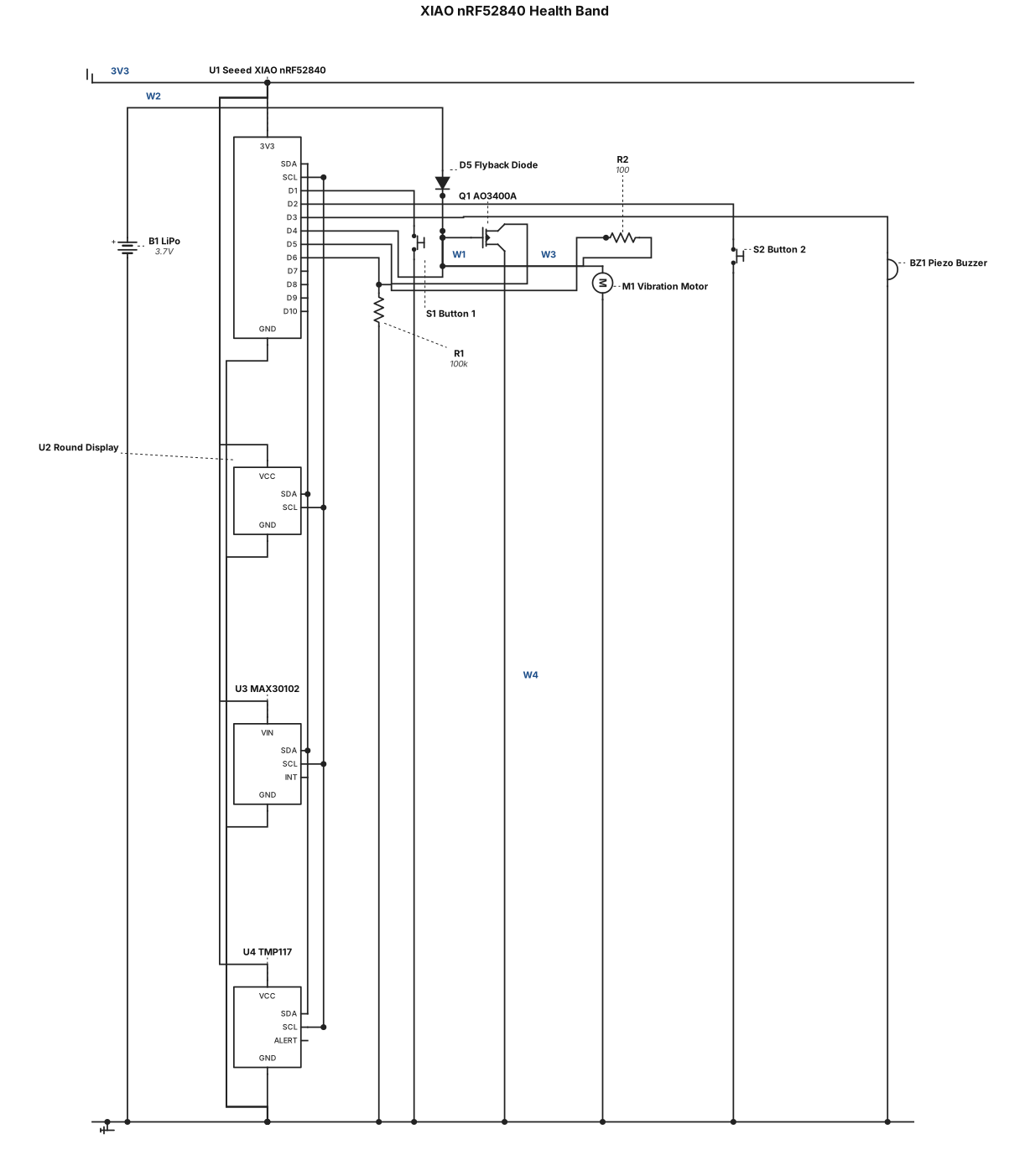
Here are all 13 components in the circuit: Seeed XIAO nRF52840 Seeed Round Display (XIAO header stack) MAX30102 heart-rate and SpO₂ sensor TMP117 temperature sensor Button 1 (6×6 mm) Button 2 (6×6 mm) Piezo buzzer Coin vibration motor (8–10 mm) AO3400A N-channel MOSFET Motor flyback diode 3.7 V LiPo battery MOSFET gate pull-down resistor (100 kΩ) MOSFET gate series resistor
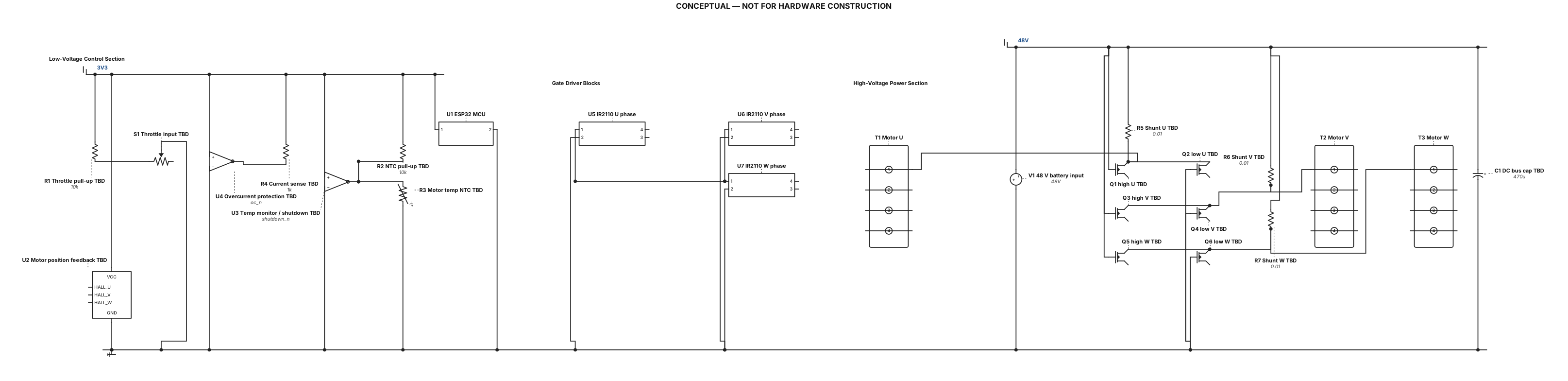
Create a conceptual electronic schematic for a Portable Emergency BLDC Motor Controller for a 48 V electric scooter. Show these functional blocks with standard electronic symbols and clear labels: 1. ESP32 microcontroller 2. Throttle input 3. Motor position feedback input 4. Three-phase inverter with six N-channel MOSFETs 5. Three IR2110 gate-driver blocks 6. Current-sensing and overcurrent protection block 7. Temperature monitoring and emergency shutdown 8. DC supply input and three motor outputs labelled U, V, W. Separate the low-voltage control section from the high-voltage power section. Label all functional connections. Mark unverified pin connections and component values as TBD. Do not invent connections. Title the drawing "CONCEPTUAL — NOT FOR HARDWARE CONSTRUCTION".
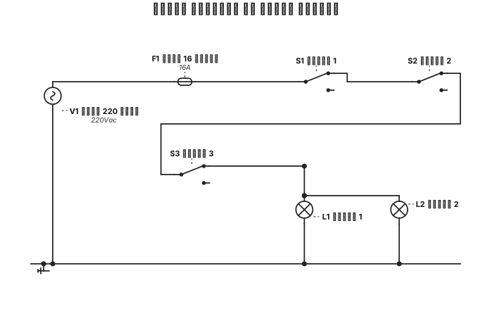
دائرة لتشغيل مصباحين من ثلاثة مفاتيح بالرسم التنفيذي
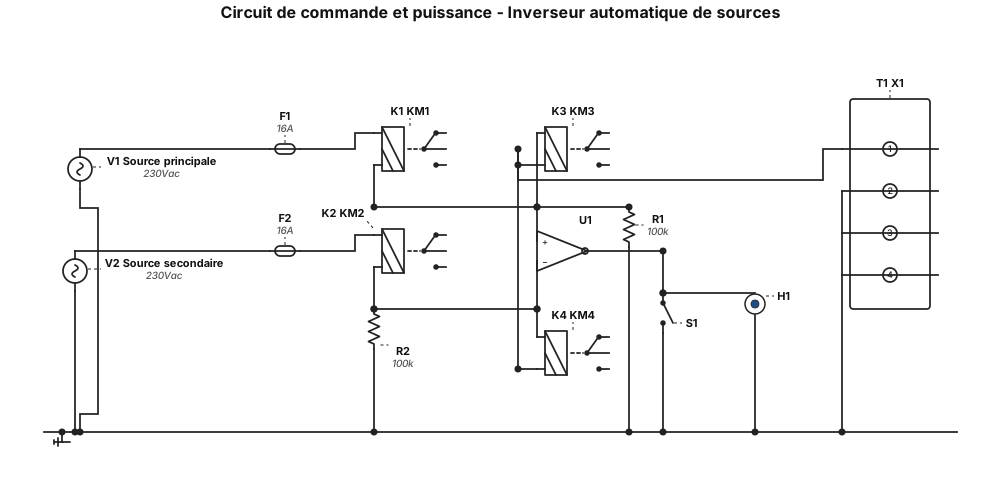
Schématisez le circuit de commande et puissance d'un inverseur automatique des sources de tension, avec repérage
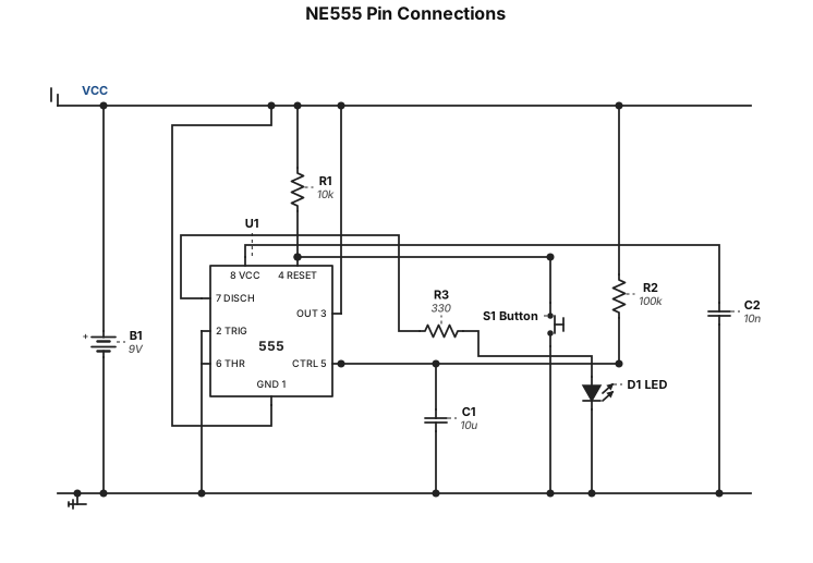
NE555 के पिन कनेक्शन पिन कनेक्शन 1 (GND) बैटरी का नेगेटिव (−) 8 (VCC) बैटरी का पॉजिटिव (+) 4 (RESET) पिन 8 / पॉजिटिव 2 (TRIGGER) 10 kΩ से पॉजिटिव; बटन से GND 6 (THRESHOLD) पिन 7 और टाइमिंग नोड से जुड़ा 7 (DISCHARGE) टाइमिंग रेज़िस्टर और पिन 6 के नोड से जुड़ा 3 (OUTPUT) 330 Ω रेज़िस्टर → LED का लंबा पैर; LED का छोटा पैर GND 5 (CONTROL) 10 nF कैपेसिटर से GND (वैकल्पिक, बेहतर स्थिरता के लिए)
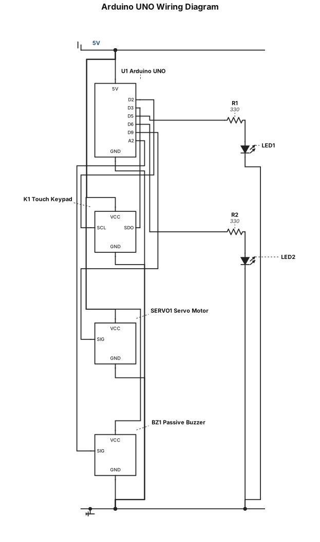
Create a clean, accurate Arduino UNO wiring diagram that fits on a single A4 sheet in landscape orientation. Use realistic electronic components, a white background, and a neat, uncluttered layout with clearly visible pin labels and wires. Connect the 4-pin touch keypad as follows: VCC to Arduino 5V, GND to GND, SCL to D2, and SDO to D3. Connect two LEDs to Arduino D5 and D6, each with its own 330-ohm series resistor and its cathode connected to GND. Connect the servo motor's power wire to 5V, ground wire to GND, and signal wire to D9. Connect the 3-pin passive buzzer module's VCC to 5V, GND to GND, and signal pin (SIG/S) to A2. Use red wires for 5V, black for GND, and different colors for signal wires. Arrange components around the Arduino with short, orderly wires and minimal crossings. Clearly label every connection and ensure that wires do not obscure pins or components. Follow the specified connections exactly. Do not add or change any connections, omit components, or create short circuits between 5V and GND. Prioritize electrical accuracy and readability. Generate a practical, component-based wiring illustration, not an abstract schematic, and ensure the complete diagram fits within the A4 page margins.
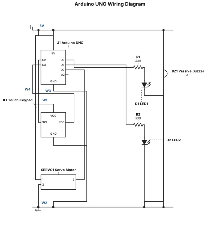
I have an Arduino UNO circuit. This circuit uses 2 LEDs, a passive buzzer, a servo motor, an Arduino UNO, and a touch keypad. The connections in this circuit are as follows: The VCC pin of the touch keypad is connected to any 5V pin on the Arduino. The GND pin is connected to any GND pin on the Arduino. The SCL pin is connected to Arduino pin D2, and finally, the SDO pin is connected to Arduino pin D3. This completes the connections for the touch keypad. For the LEDs, the connections are made to Arduino UNO pins D5 and D6, with a 330-ohm resistor connected in series with each LED for protection. For the servo motor, its power connections are supplied through the 5V and GND pins of the Arduino UNO, while its signal connection is made through Arduino pin D9. For the buzzer, a 3-pin passive buzzer module is used. Its power is supplied through the Arduino's 5V and GND pins, and its signal connection is made through Arduino pin A2. Based on these connections, create an image of the Arduino UNO wiring diagram for this circuit, ensuring that the entire diagram fits within the dimensions of an A4 sheet of paper.
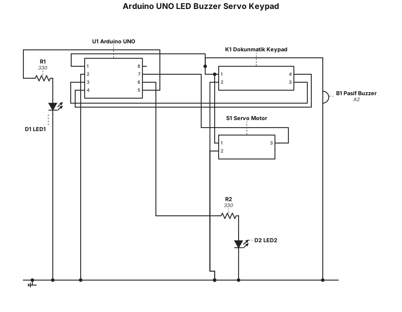
Elimde bir adet arduino UNO devresi var. Bu devrede 2 adet LED, pasif buzzer, Servo motor, Arduino UNO ve dokunmatik keypad kullanılmaktadır. Bu devrenin bağlantılarında: Dokunmatik Keypad'in VCC bacağı Arduino'nun herhangi bir 5V pinine bağlanmakta. GND bacağı ise Arduino'nun herhangi bir GND pinine bağlı. SCL bacağı ise Arduino D2 pinine bağlı, ve son olarak SDO bacağı Arduino'nun D3 pinine bağlıdır. Dokunmatik keypad için bağlantılar bu şekilde tamamlanır. LED'lerde ise bağlantı, Arduino UNO'nun D5 ve D6 pinlerine, seri bağlantılı bir 330ohm Direnç ile korunarak yapılmaktadır. Servo motorda ise, Servo motorun beslemeleri Arduino UNO'nun 5V ve GND. pinleri üzerinden, haberleşmesi ise Arduino D9 pini ile yapılmaktadır Buzzer bağlantıları ise, burada 3 bacaklı bir Pasif Buzzer Modülü kullanılmıştır. Beslemeleri Arduino'nun 5V ve GND pinleri üzerinden sağlanıp, haberleşme ise Arduino A2 pini üzerinden sağlanmaktadır. Bu bağlantılara dayanarak, bu devrenin Arduino UNO bağlantı şemasını bir A4 kağıdı boyutları içerisinde sığacak şekilde görselini oluşturunuz.
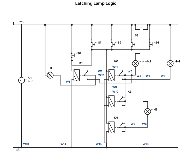
S0, S1, S2, S3, S4 – buttons/switches; H1, H2, H3, H4 – indicator lamps. Once the buttons are released, the lamps remain lit (with the exception of S4). H2 cannot be lit unless H1 is on; H3 cannot be lit unless both H1 and H2 are on. Implement the following logic: Releasing S0 turns on H3: H3 = !S0 Pressing S1 turns on H1: H1 = S1 Pressing S1 and S2 simultaneously turns on H2: H2 = S1 * S2 Pressing S1, S2, and S3 simultaneously turns on H4: H4 = S1 * S2 * S3 Pressing S4 turns off all lamps (i.e., it deactivates the latching circuits).
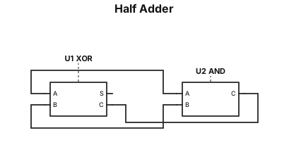
Half adder