
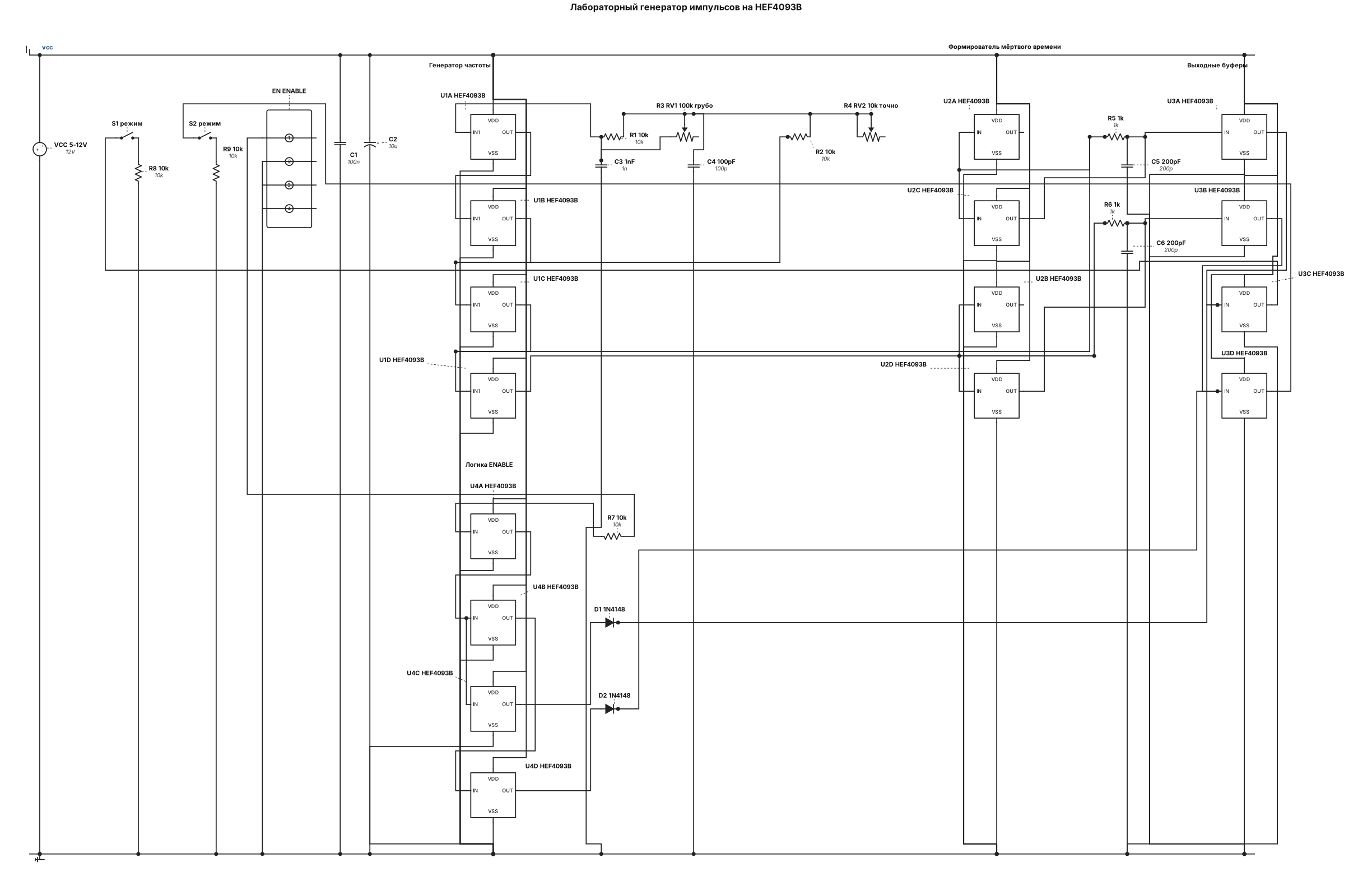
Разработай принципиальную схему лабораторного генератора импульсов на трёх микросхемах HEF4093B. Требования: - Частота регулируется в диапазоне 10–500 кГц. - Независимая регулировка скважности с помощью двух последовательно включённых потенциометров: грубого и точного. - Переключение между однотактным режимом (один выход) и двухтактным режимом (два чередующихся выхода). - Фиксированное мёртвое время между выходными импульсами, предварительная цель — 200 нс. - Питание логики стабилизированное, 5–12 В в пределах допуска микросхем. - Выходы предназначены для внешних драйверов MOSFET, например IR2113 или TC4420. - Предусмотреть вход ENABLE и защиту от одновременной активности выходов A и B. Использовать реальные компоненты, указать номера выводов каждой микросхемы, все соединения, номиналы резисторов и конденсаторов, диапазоны регулировки и расчёты временных параметров. Не выдавать непроверенные параметры за гарантированные. Если выбранная архитектура не обеспечивает 10–500 кГц, независимую скважность и мёртвое время 200 нс одновременно, объяснить ограничение и предложить исправление. Сначала создать схему, затем проверить её соединения и выполнить переходное моделирование на 10, 100 и 500 кГц. Показать осциллограммы обоих выходов и измеренное мёртвое время.
Engineering Diagram Examples from Real Specifications
Browse eligible circuit, ladder, single-line, P&ID, breadboard, timing, and logic drawings with their original prompts.
Browse 549 real creationsMain engineering studio
Showing 337–360 of 381. No stock examples or system defaults. Choose a tool, study a real result, then reopen its prompt as your starting point.
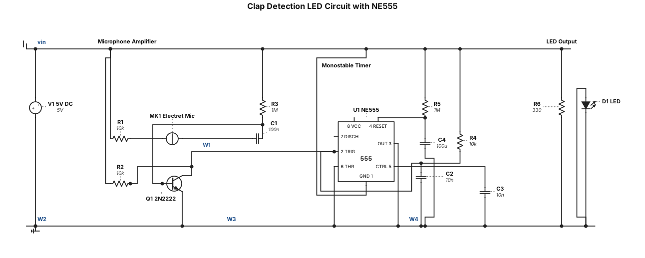
Generate a complete electronic circuit schematic for a clap detection LED circuit using an NE555 timer IC. Requirements: - Use a microphone to detect a hand clap. - Use a transistor amplifier to amplify the microphone signal. - Use the NE555 timer in monostable mode. - Turn an LED ON for approximately 2 seconds after detecting a clap, then turn it OFF automatically. - Use a regulated 5V DC supply. - Show all 555 timer pin numbers, resistor and capacitor values, transistor connections, microphone connections, LED polarity, and power supply connections. - Include a complete bill of materials. - Make the circuit suitable for a beginner to assemble on a breadboard. - Check the circuit for incorrect or missing connections. - Provide a clear, labelled schematic rather than a decorative illustration.
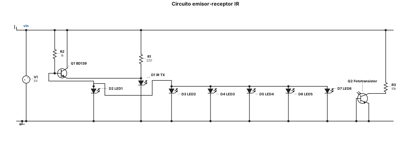
🧾 Materiales del circuito - 1 transistor BD139 - 1 diodo emisor infrarrojo (IR tx) - 1 led Fototransitor - 6 leds - 6 iodos - 1 resistencia para el emisor IRs - resistencia de 1kohmios - Cable para conexiones - Fuente de alimentación
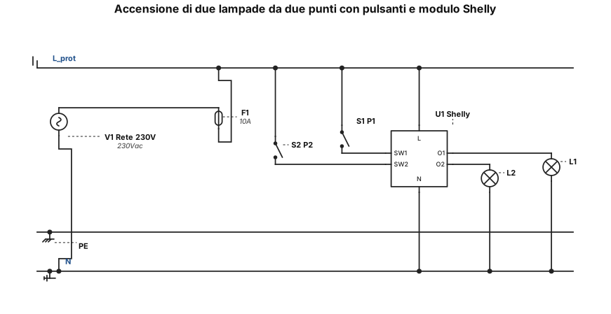
**PROGETTO: SCHEMA ELETTRICO DI ACCENSIONE DI DUE LAMPADE DA DUE PUNTI CON DUE PULSANTI E MODULO SHELLY** Realizzare uno schema elettrico dettagliato, chiaro e leggibile, con collegamenti reali tra i morsetti dei componenti. Non realizzare una semplice piantina e non usare collegamenti indicativi. **Componenti** * Due lampade: L1 e L2. * Due pulsanti momentanei normalmente aperti: P1 e P2. * Un modulo Shelly, con morsetti identificati esattamente secondo il modello utilizzato. * Alimentazione di rete 230 V AC: fase L, neutro N e conduttore di protezione PE. * Scatole da incasso 503 per i componenti previsti. **Funzionamento richiesto** Entrambi i pulsanti devono comandare l'accensione e lo spegnimento delle due lampade da entrambi i punti di comando, secondo la logica prevista dal modulo Shelly. Le due lampade devono accendersi e spegnersi insieme. **Come deve essere disegnato lo schema** 1. Disegnare ogni componente separatamente e assegnargli un'etichetta univoca. 2. Mostrare i morsetti reali del modulo Shelly e i contatti dei due pulsanti. 3. Tracciare ogni singolo filo dal morsetto di partenza a quello di arrivo. 4. Indicare vicino a ogni filo il nome del conduttore e la sua destinazione. 5. Mostrare chiaramente le giunzioni elettriche con punti di connessione; nessun incrocio deve essere interpretato come una giunzione se non è indicato. 6. Separare graficamente i collegamenti di alimentazione, comando e uscita verso le lampade. 7. Inserire una legenda dei conduttori e una tabella con origine e destinazione di ogni filo. 8. Non inventare morsetti, componenti o collegamenti. Se mancano informazioni indispensabili, indicarle prima di completare lo schema. **Risultato richiesto** Un unico schema elettrico completo, con linee ordinate, senza fili sovrapposti, con morsetti e connessioni leggibili anche sullo schermo di un telefono. Deve essere possibile seguire ogni filo dalla partenza all'arrivo senza ambiguità.
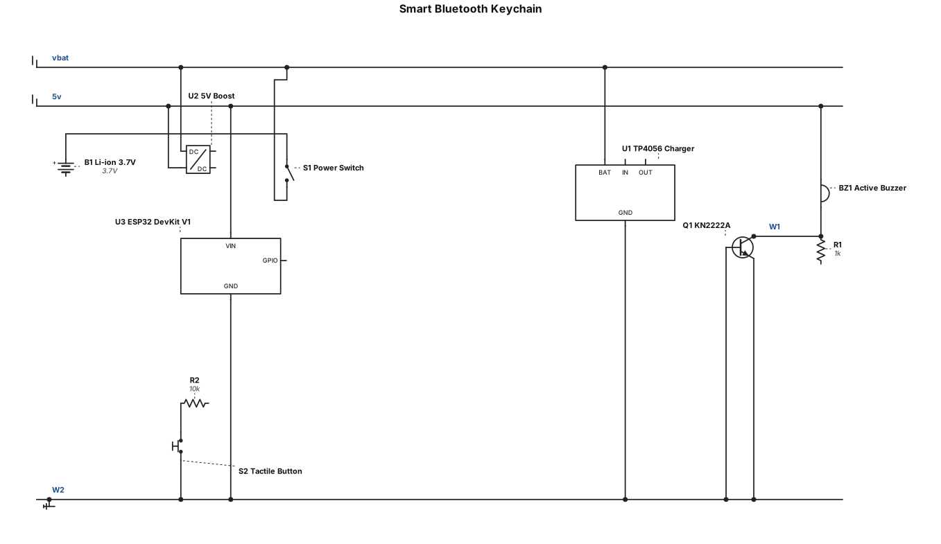
Project Title: Smart Bluetooth Keychain Problem Statement: Keys are frequently misplaced or lost, causing inconvenience and wasting time. Traditional keychains only hold keys and do not provide any tracking or alert functionality. The Smart Bluetooth Keychain aims to solve this problem by using an ESP32 and Bluetooth Low Energy (BLE) to detect disconnection from an Android phone and activate a buzzer alert when the Bluetooth connection is lost. Components Required: 1. ESP32 DevKit V1 2. Active buzzer 3. Protected rechargeable 3.7 V Li-ion battery 4. TP4056 battery charging module 5. 5 V boost converter module 6. Mini on/off slide switch 7. Tactile push button 8. KN2222A NPN transistor 9. Base resistor 10. Jumper wires 11. Plastic enclosure 12. Key ring
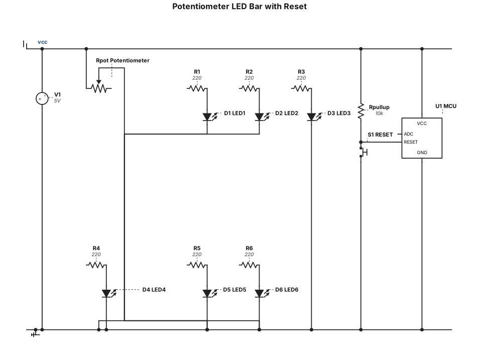
Create a circuit with a potentiometer, 6 LEDs, and a RESET button. Map the potentiometer's ADC value to a range of 0–9. Control the LEDs progressively: values 0–2 turn on LED 1, values 3–4 turn on LEDs 1–2, value 5 turns on LEDs 1–3, value 6 turns on LEDs 1–4, value 7 turns on LEDs 1–5, and values 8–9 turn on all 6 LEDs. Pressing RESET resets the counter to 0 and turns off all LEDs. Provide the circuit diagram, component list, wiring, and complete working code. Ask me which microcontroller I use if it is not specified.
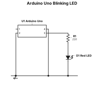
A breadboard wiring diagram for an Arduino Uno blinking one red LED from pin 13 through a 220 ohm resistor, with ground returned to the rail.
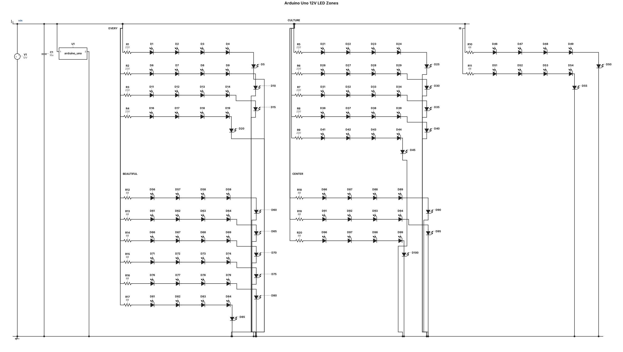
Create a workable 12V 1A circuit schematic with an Arduino Uno at the center. Use a 10µF capacitor across the main 12V power and GND rails for filtering. Total 100 LEDs divided into 5 parallel zones running at 20mA per branch: 1. "EVERY": 20 Red LEDs (4 branches of 5 LEDs in series with a 220Ω resistor). 2. "CULTURE": 25 Orange LEDs (5 branches of 5 LEDs in series with a 220Ω resistor). 3. "IS": 10 White LEDs (2 branches of 5 LEDs in series with a 68Ω resistor). 4. "BEAUTIFUL": 30 Green LEDs (6 branches of 5 LEDs in series with a 68Ω resistor). 5. "CENTER": 15 Blue LEDs (3 branches of 5 LEDs in series with a 68Ω resistor). Connect all branch positive sides to the 12V rail and all final negative cathodes to the common GND rail connected to Arduino GND. Output a clean schematic diagram.
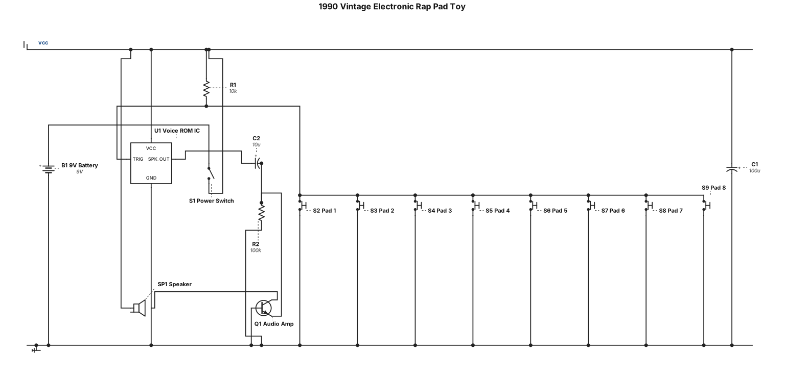
Schematic for 1990 vintage electronic rap pad toy
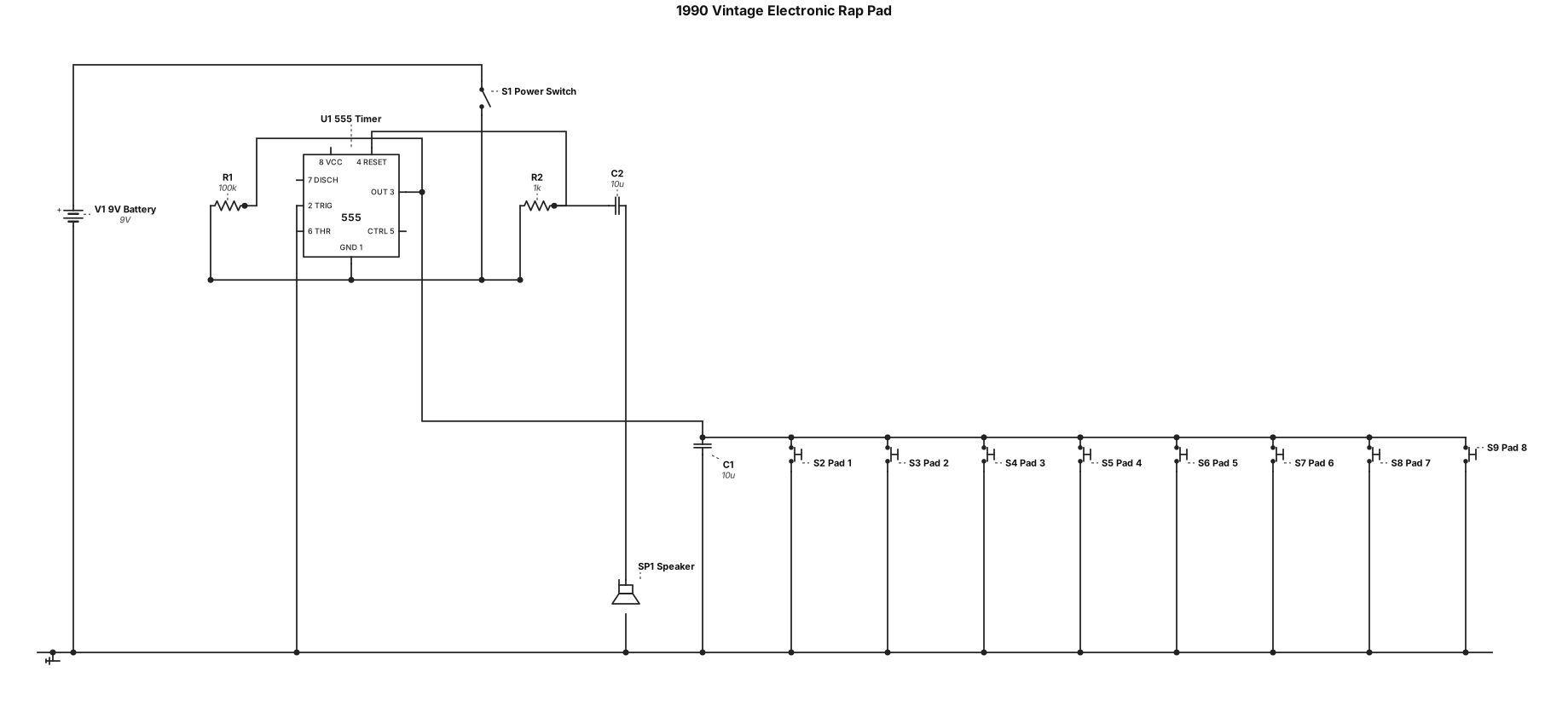
Schematic for 1990 vintage electronic rap pad
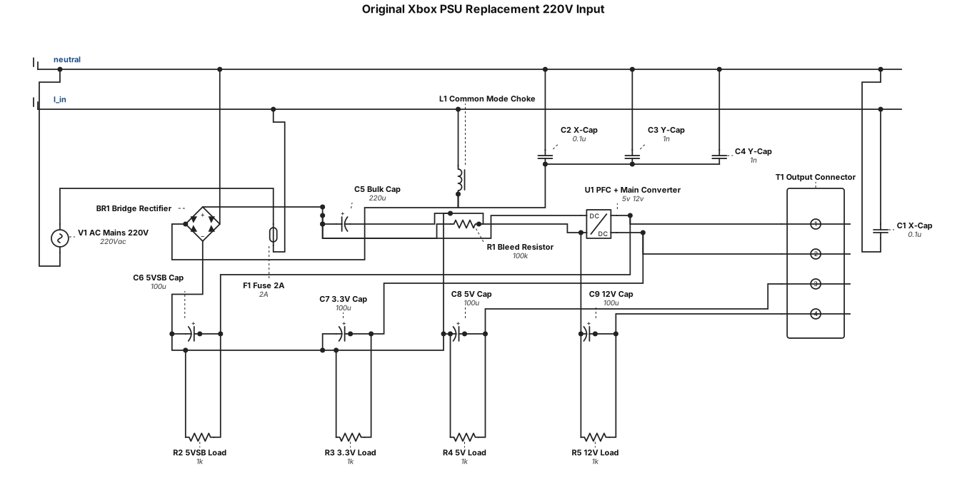
Original xbox psu replacement for 220v input
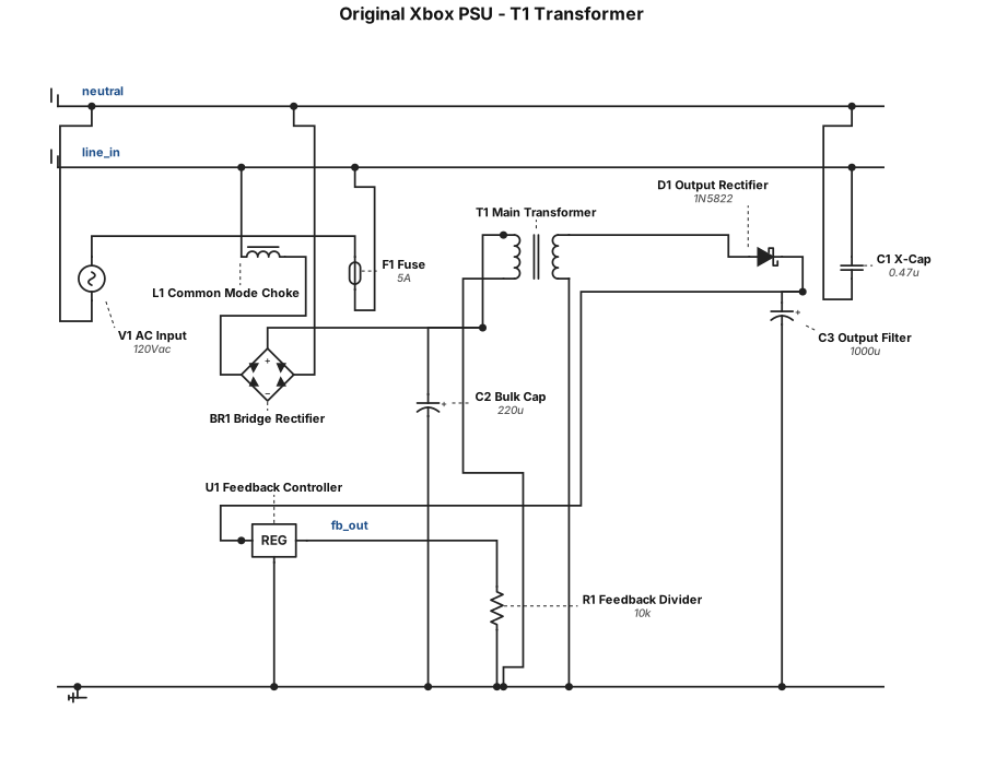
Original xbox psu replacement what is part t1 specs
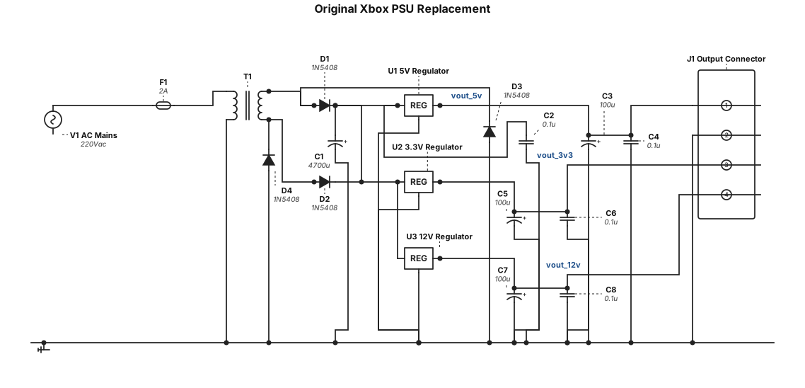
Original xbox psu replacement
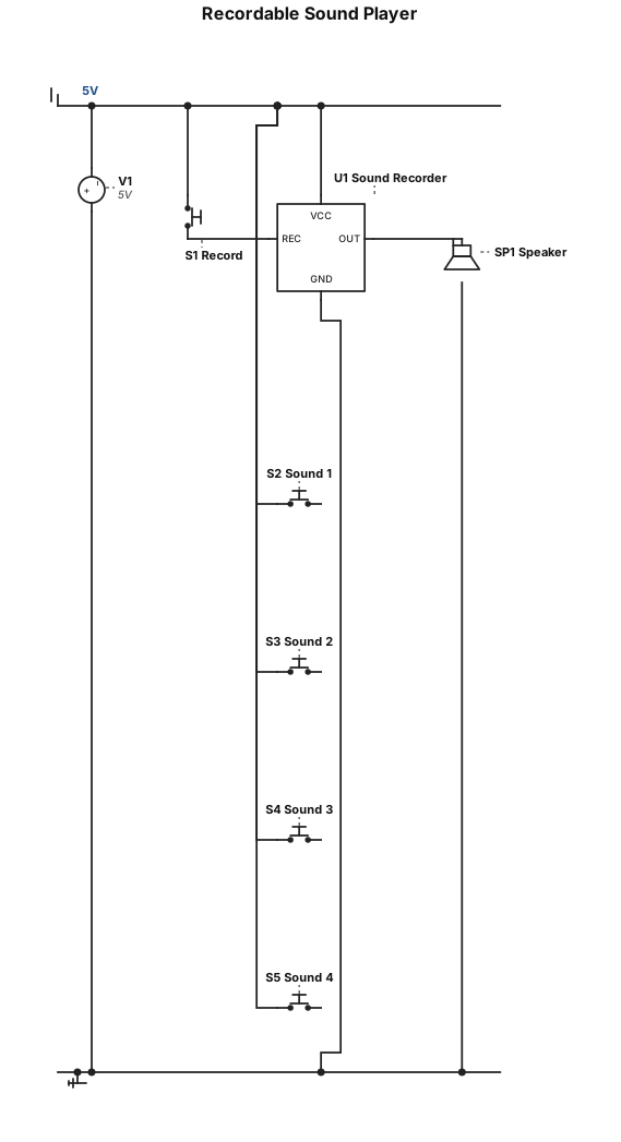
4 buttons to play different recordable sounds. 5v circuit. Record own sounds output to speaker
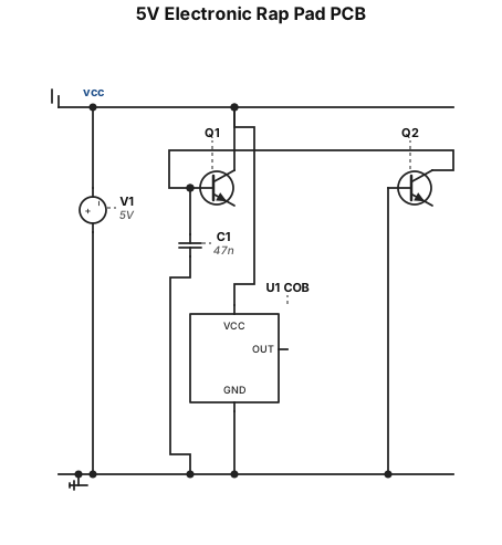
5v electronic rap pad PCB known components include one 2n2222 a331 transistor and a 47nf cap and a cob
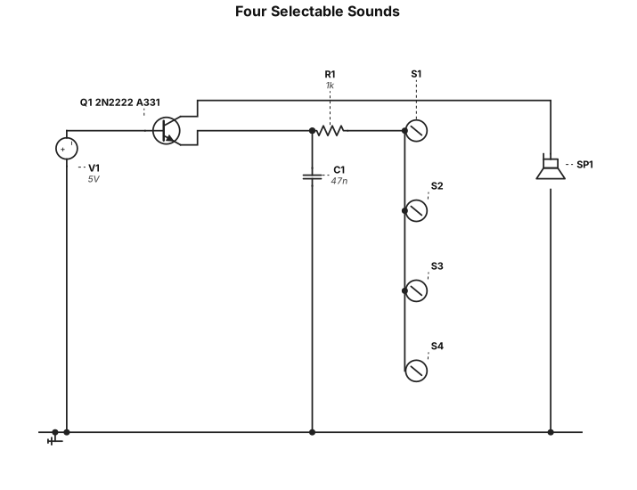
5v circuit four selectable sounds and a common signal. Sounds playback to speaker. has a single resistor. one 2n2222 a331 transistor and a 47nf capacitor no other components
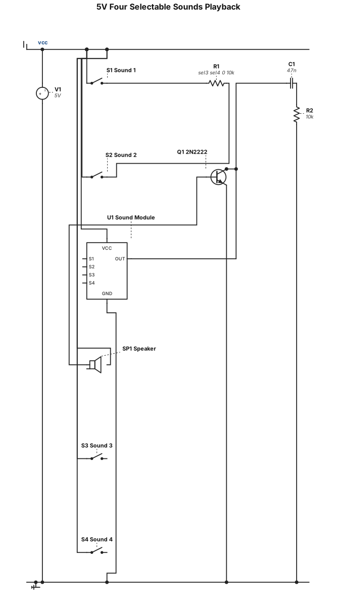
5v circuit four selectable sounds playback to speaker has a single resistor one 2n2222 a331 transistor and a 47nf capacitor

Create a clear preliminary electronics interconnection schematic for the HSI portable imaging research system. Known equipment: - Raspberry Pi 5 (4 GB) - Raspberry Pi Camera Module 3 - 7-inch touchscreen display - 64 GB microSD card - External power supply; exact model and electrical rating still need verification Show only connections that can be supported by the selected hardware documentation: - Camera Module 3 connected to the Raspberry Pi through the compatible camera interface. - microSD storage associated with the Raspberry Pi. - Touchscreen display connected through its verified interface, to be confirmed from the exact display model. - Power input to the Raspberry Pi and any separate display power input only after their required ratings and wiring have been verified. Use standard schematic symbols, clearly labelled components, distinct power/data connections and a legend. Do not guess GPIO pins, connector pin numbers, display interface, voltage/current ratings, grounding, regulator circuitry or wiring. Mark unverified connections as “TO VERIFY — exact model/datasheet required” instead of drawing fabricated connections. Title the drawing “HSI System — Preliminary Electronics Interconnection Diagram”. Add a note: “For presentation planning only. Verify against the actual hardware, manufacturer datasheets and physical wiring before use.” Do not include the Ocean QE Pro-ABS spectrometer in the device circuit because it is separate calibration/validation equipment.
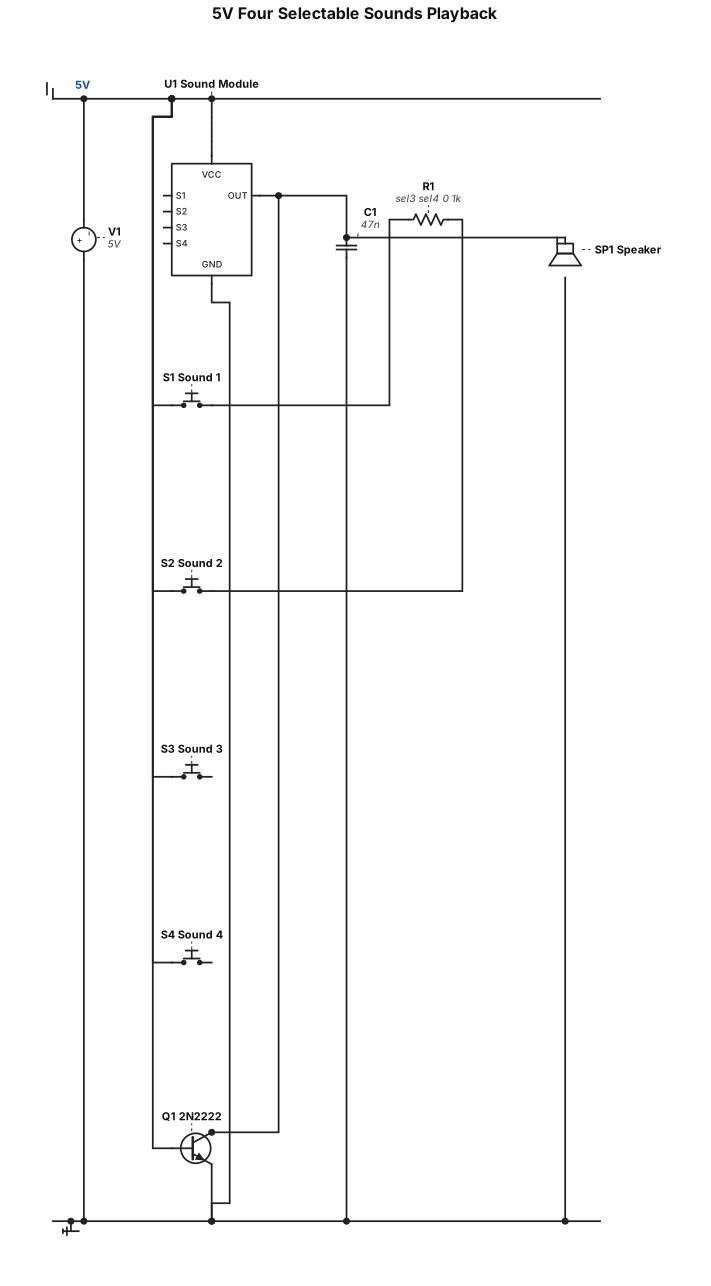
5v circuit four selectable sounds playback to speaker has a single 1k resistor one 2n2222 a331 transistor and a 47nf capacitor
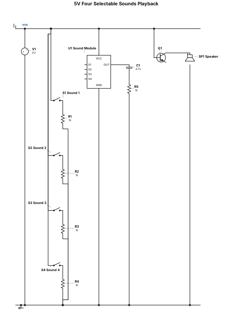
5v circuit four selectable sounds playback to speaker has a 1k resistor one 2n2222 a331 transistor and a 47nf capacitor
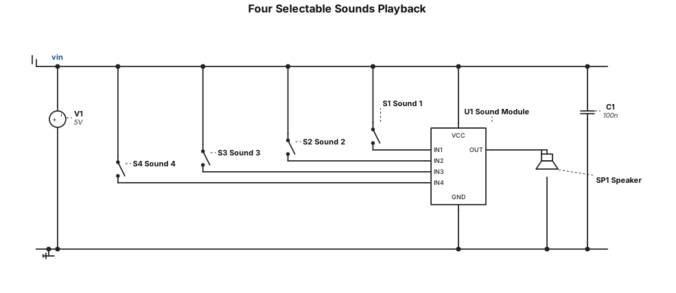
5v circuit four selectable sounds playback to speaker
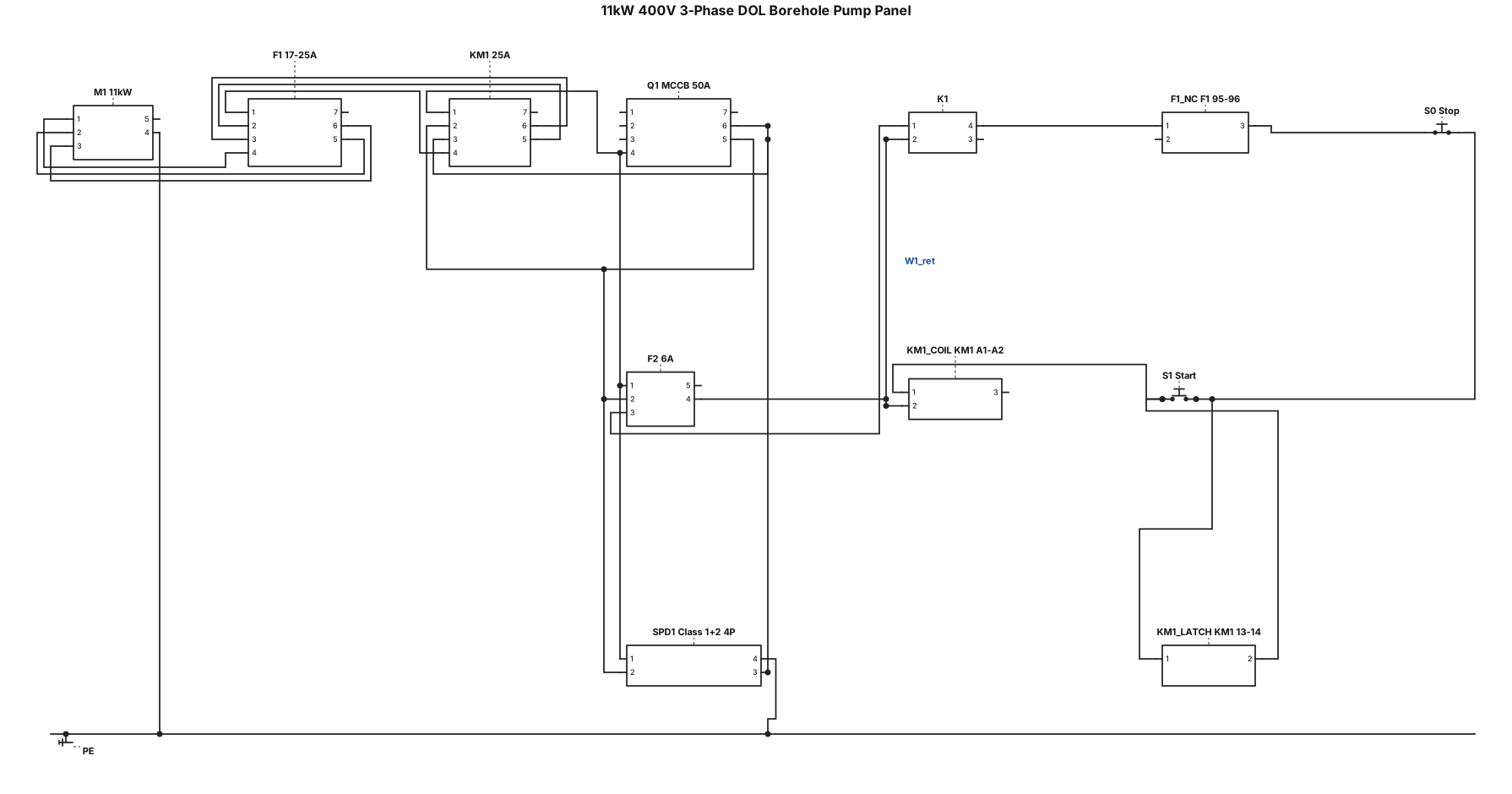
Generate a 2D IEC 60617 electrical schematic for an 11 kW 400V 3-Phase DOL Borehole Pump Panel. POWER CIRCUIT (400VAC 3-Phase + PE, No Neutral): - Terminals L1, L2, L3, PE. - Main Breaker Q1 (50A 3P MCCB). - Surge Protector SPD1 (Class 1+2 4P) downstream of Q1 across L1, L2, L3 to PE. - Contactor KM1 (25A 3P) feeding Thermal Overload F1 (17-25A). - Motor terminals U1, V1, W1 feeding 11 kW Motor M1 with frame PE ground. CONTROL CIRCUIT (400VAC L1-L2 Supply): - Control MCB F2 (6A 2P) across L1 and L2. - Phase Angle/Sequence Relay K1 (NO contact 11-14) in series. - Thermal Overload F1 (NC contact 95-96) in series. - NC Stop Button S0 in series. - NO Start Button S1 in parallel with KM1 NO Latch (13-14). - 400VAC Contactor Coil KM1 (A1-A2) back to L2 via F2
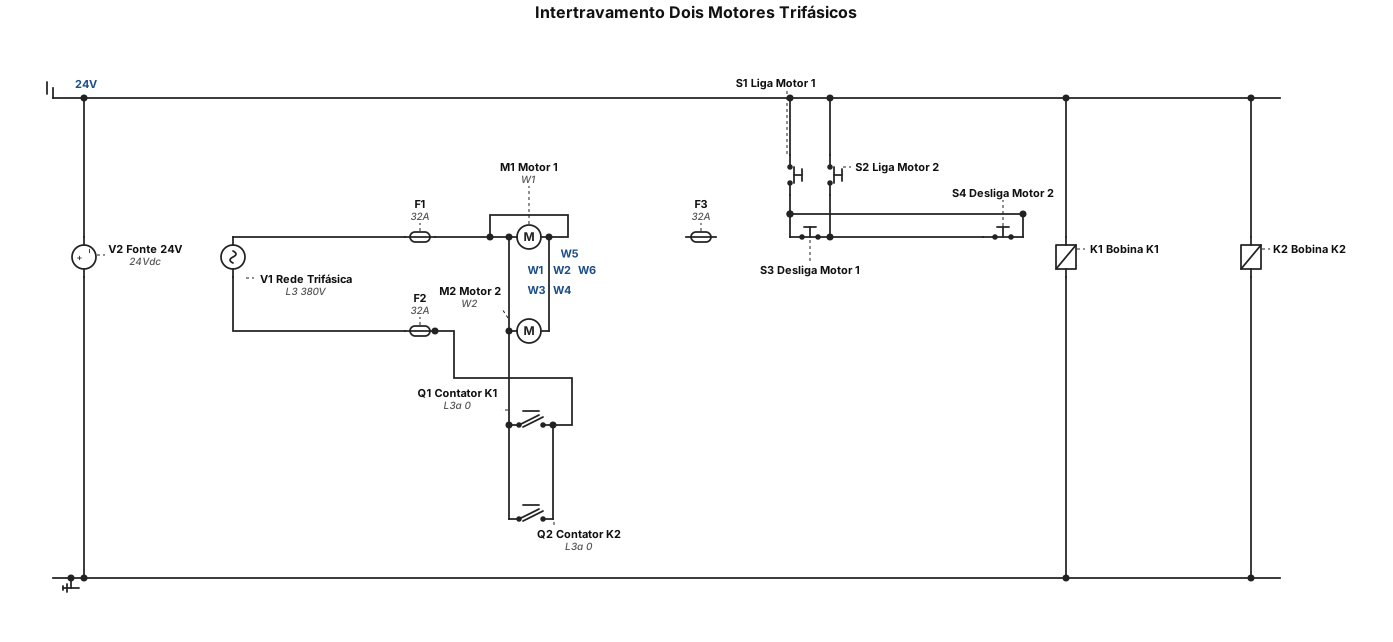
faça um diagrama de intertravamento com dois motores trifásico
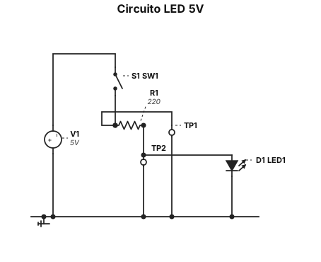
un circuito LED da 5 V con una resistenza in serie da 220 Q, un interruttore SPST e punti di test prima e dopo la resistenza