
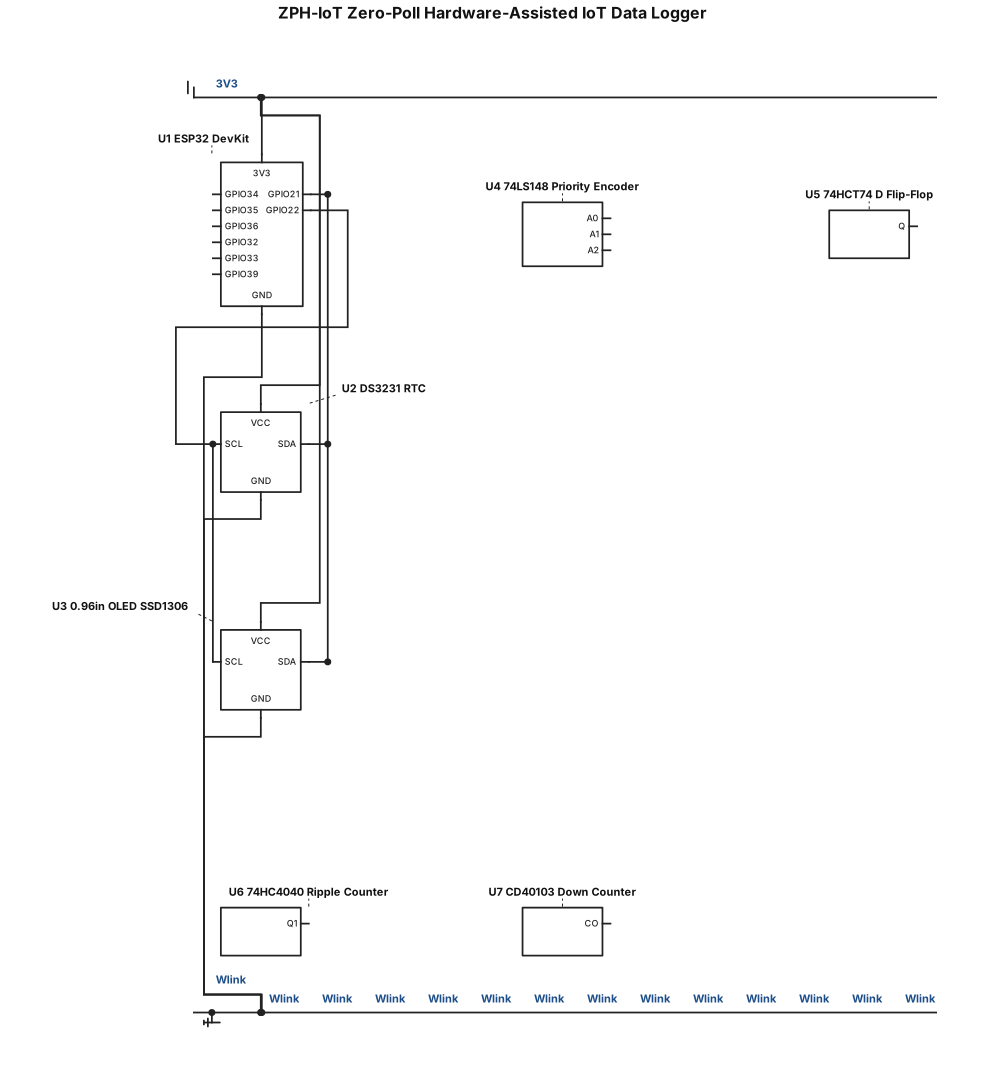
Create a clean, professional electronic hardware schematic for: ZPH-IoT (Zero-Poll Hardware-Assisted IoT Data Logger) Include these components: - U1: ESP32 DevKit - U2: DS3231 RTC Module - U3: 0.96-inch I2C OLED Display (SSD1306) - U4: 74LS148 Priority Encoder - U5: 74HCT74 D-Type Flip-Flop - U6: 74HC4040 Ripple Counter - U7: CD40103 Programmable Down Counter Place the four logic ICs on the left, the ESP32 in the center, and the RTC and OLED on the right. Make these connections: **Logic outputs to ESP32:** - 74LS148 A0 → ESP32 GPIO34 - 74LS148 A1 → ESP32 GPIO35 - 74LS148 A2 → ESP32 GPIO36 - 74HCT74 Q → ESP32 GPIO32 - 74HC4040 Q1 → ESP32 GPIO33 - CD40103 CO → ESP32 GPIO39 **I2C connections:** - ESP32 GPIO21 (SDA) → DS3231 SDA and OLED SDA - ESP32 GPIO22 (SCL) → DS3231 SCL and OLED SCL **Power:** - ESP32 3V3 → DS3231 VCC and OLED VCC - Common GND → ESP32, DS3231, and OLED Clearly label all important pins and signals by name, including GPIO21, GPIO22, GPIO32–GPIO36, GPIO39, SDA, SCL, A0, A1, A2, Q, Q1, and CO. Use clean straight wires, minimal crossings, junction dots where needed, and a white background suitable for an engineering project report. Do not use generic numbered pins or random wire labels such as W1, W2, W3. Do not invent unspecified internal connections for the logic ICs.
Engineering Diagram Examples from Real Specifications
Browse eligible circuit, ladder, single-line, P&ID, breadboard, timing, and logic drawings with their original prompts.
Browse 540 real creationsAll visitor creations
Showing 97–120 of 540. No stock examples or system defaults. Choose a tool, study a real result, then reopen its prompt as your starting point.
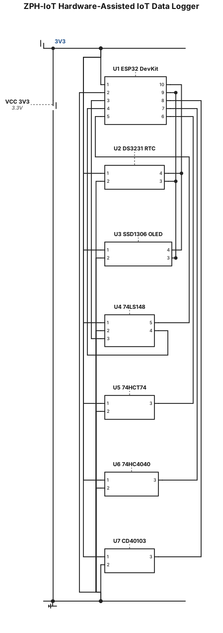
Draw a clean electronic schematic titled: ZPH-IoT Hardware-Assisted IoT Data Logger Include these components: U1 ESP32 DevKit U2 DS3231 RTC module U3 SSD1306 0.96-inch I2C OLED U4 74LS148 Priority Encoder U5 74HCT74 D-Type Flip-Flop U6 74HC4040 Binary Ripple Counter U7 CD40103 Presettable Down Counter Connect the logic IC outputs to the ESP32 as follows: 74LS148 A0 → ESP32 GPIO34 74LS148 A1 → ESP32 GPIO35 74LS148 A2 → ESP32 GPIO36 74HCT74 Q → ESP32 GPIO32 74HC4040 Q1 → ESP32 GPIO33 CD40103 CO → ESP32 GPIO39 Connect the I2C peripherals: ESP32 GPIO21 → DS3231 SDA and SSD1306 SDA ESP32 GPIO22 → DS3231 SCL and SSD1306 SCL Use common 3.3V power and common ground for ESP32, DS3231 and OLED. Create a neat schematic with the four logic ICs on the left, the ESP32 in the center, and the RTC and OLED on the right. Clearly label all components and pins. Use clean straight wires and junction dots. No block diagram. No autogenerated wire labels such as W1, W2, W3. White background, professional academic report style.
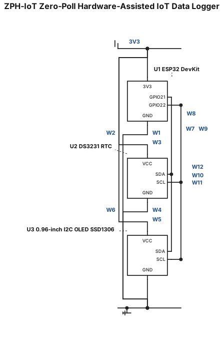
Create a clean professional schematic diagram for an academic IoT project titled: ZPH-IoT (Zero-Poll Hardware-Assisted IoT Data Logger) Use these three components: 1. ESP32 DevKit development board 2. DS3231 Real-Time Clock (RTC) module 3. 0.96-inch SSD1306 I2C OLED display module The ESP32 is the main microcontroller. Make the following connections: ESP32 GPIO21 (SDA) → DS3231 SDA and OLED SDA ESP32 GPIO22 (SCL) → DS3231 SCL and OLED SCL ESP32 3V3 → DS3231 VCC and OLED VCC ESP32 GND → DS3231 GND and OLED GND The DS3231 RTC and SSD1306 OLED share the same I2C bus. Use a common 3.3V power supply and common ground. Clearly label all components and pins: U1: ESP32 DevKit U2: DS3231 RTC U3: 0.96-inch I2C OLED SSD1306 Create a neat electronic schematic with clear SDA and SCL connections, junction dots at branches, and no unnecessary wire crossings. Do not create a block diagram. Generate a complete circuit schematic suitable for an engineering project report.
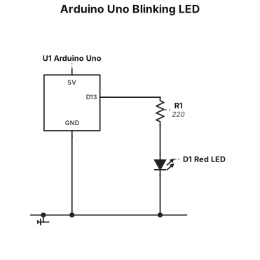
A breadboard wiring diagram for an Arduino Uno blinking one red LED from pin 13 through a 220 ohm resistor, with ground returned to the rail.
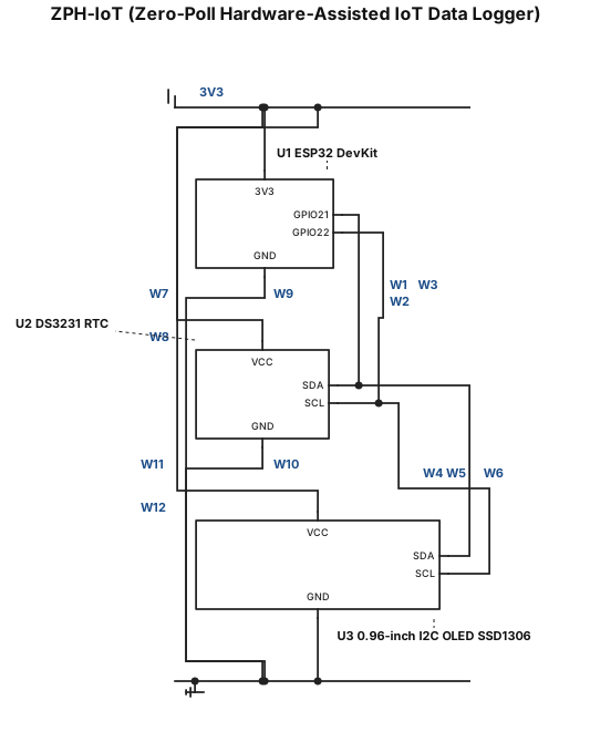
Create a clean, professional, report-ready electronic circuit diagram for an IoT project titled: “ZPH-IoT (Zero-Poll Hardware-Assisted IoT Data Logger)” The circuit should contain the following components: 1. ESP32 Development Board (ESP32 DevKit) 2. RTC module (DS3231) 3. OLED Display Module (0.96-inch I2C OLED, SSD1306) CONNECTION REQUIREMENTS: Use the ESP32 as the main microcontroller. Connect both the DS3231 RTC module and the OLED display using the ESP32 I2C bus. ESP32 GPIO 21 → SDA pin of DS3231 RTC ESP32 GPIO 22 → SCL pin of DS3231 RTC ESP32 GPIO 21 → SDA pin of OLED display ESP32 GPIO 22 → SCL pin of OLED display ESP32 3.3V → VCC pin of DS3231 RTC ESP32 3.3V → VCC pin of OLED display ESP32 GND → GND pin of DS3231 RTC ESP32 GND → GND pin of OLED display IMPORTANT DESIGN REQUIREMENTS: Generate a clear, visually organized circuit diagram suitable for insertion into an academic engineering project report. Prefer a breadboard-style physical wiring diagram similar to a Tinkercad circuit view, showing the actual ESP32 board, DS3231 RTC module, OLED module, and visible jumper wire connections. Clearly label all components and important pins. Use neat wire routing with no unnecessary crossing wires. Show common SDA and SCL connections clearly, since both the RTC and OLED share the same I2C bus. The ESP32 should be positioned centrally or clearly as the main controller, with the RTC and OLED connected logically around it. Use a clean white or light background suitable for a technical report. The final output should look realistic, professional, and easy to understand at first glance. Do NOT generate a conceptual block diagram. Do NOT omit any power or ground connections. Generate the complete final circuit diagram as a polished engineering visualization.
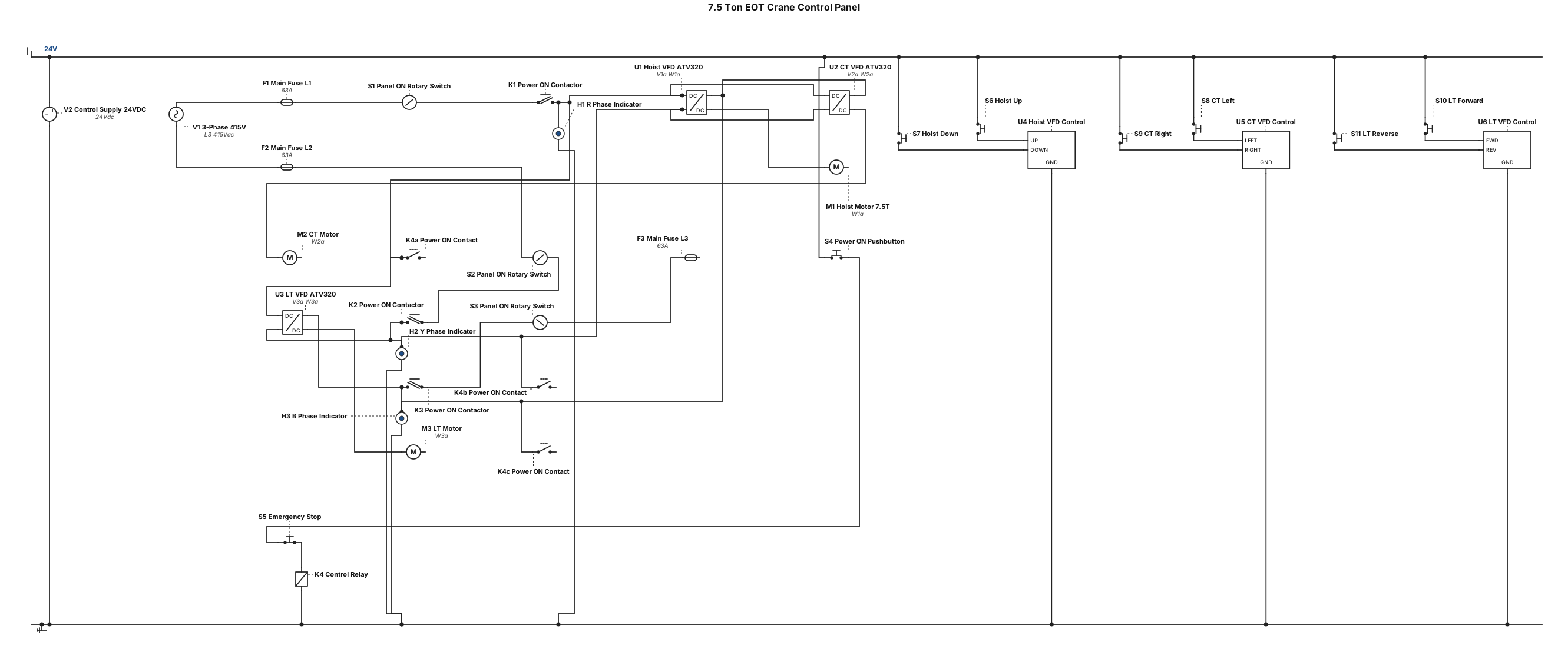
i want to create a electric control panel wiring drawing for 7.5 Ton EOT Crane with Hoisting ,CT ,LT with Pendent control, pendent has Emergency,Power on,Up&Dwn,CT left & right ,LT Fwd,Rvs with power on contactor and outside panel there should be rotary switch for panel on and RYP Light indicator, that should on when control on button press,Hoist,CT, LT all should have VFD schneider altiver 320
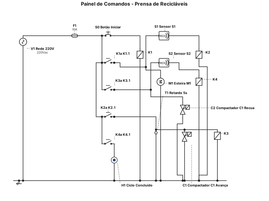
A empresa LionTech contratou sua equipe técnica para projetar um painel de comandos elétricos destinado a uma prensa de materiais recicláveis. O sistema é composto por uma esteira de entrada (M1), um compactador hidráulico (C1), dois sensores de presença (S1, S2) e uma lâmpada de ciclo concluído. O sistema deve atender aos seguintes requisitos: O ciclo de compactação é iniciado com o acionamento de um botão, que liga a esteira M1; Quando o sensor 51 detecta material suficiente, a esteira para, e o compactador C1 avança; O compactador C1 deve recuar após um retardo de 5 segundos; O ciclo é finalizado quando o sensor S2 é ativado, e a lâmpada de ciclo concluído acende; A esteira M1 só pode ser reativada após o recuo do compactador C1.
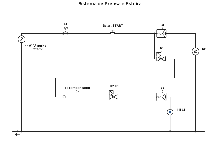
Explicação do funcionamento "Inicialmente, ao pressionarmos o botão START, a esteira M1 é acionada e começa a transportar os materiais recicláveis até a prensa. Quando o sensor S1 identifica que há material suficiente, a esteira é desligada automaticamente e o compactador C1 inicia seu movimento de avanço, realizando a compactação do material. Após o avanço, o compactador permanece nessa posição durante 5 segundos, conforme o tempo programado no temporizador. Finalizado esse tempo, o compactador C1 inicia seu movimento de recuo, retornando à posição inicial. Quando o sensor S2 é ativado, o sistema identifica a conclusão do ciclo e acende a lâmpada de sinalização, indicando que a compactação foi finalizada. Por fim, após o retorno completo do compactador, a esteira M1 fica liberada para ser acionada novamente, permitindo o início de um novo ciclo de funcionamento."
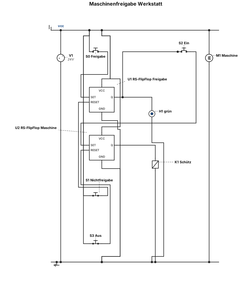
In einer Werkstätte arbeitet ein Arbeiter an einer Maschine. Diese Maschine wird durch den Meister freigegeben (S0) bzw. nicht freigegeben (S1), ist die Maschine freigegeben leuchtet zusätzlich eine grüne Lampe (H1). Der Arbeiter kann seine Maschine ein- bzw. ausschalten (S2 & S3), solange sie freigegeben ist. Betätigt des Meister den Nichtfreigabetaster, läuft die Maschine weiter solange bis sie ausgeschaltet wird, sie kann allerdings nicht mehr eingeschaltet werden. Hinweis: Verwenden Sie dafür sogenannte RS-Flip Flops und beschreiben sie diese vorher.
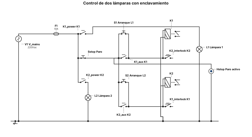
El encendido de dos lamparas, con las siguienta condiciones: tendra un solo boton de paro, Cada lampara tendra su boton de arranque Cuando sea energizado la lámpara primera la lampara, la lámpara segunda no podrá energizarse. La segunda lampara solo podra ser energizada si la primera se energiza > con boton de paro. Si esta energizada la segunda lampara la primera no podrá ser energizada El paro también debe ser indicado
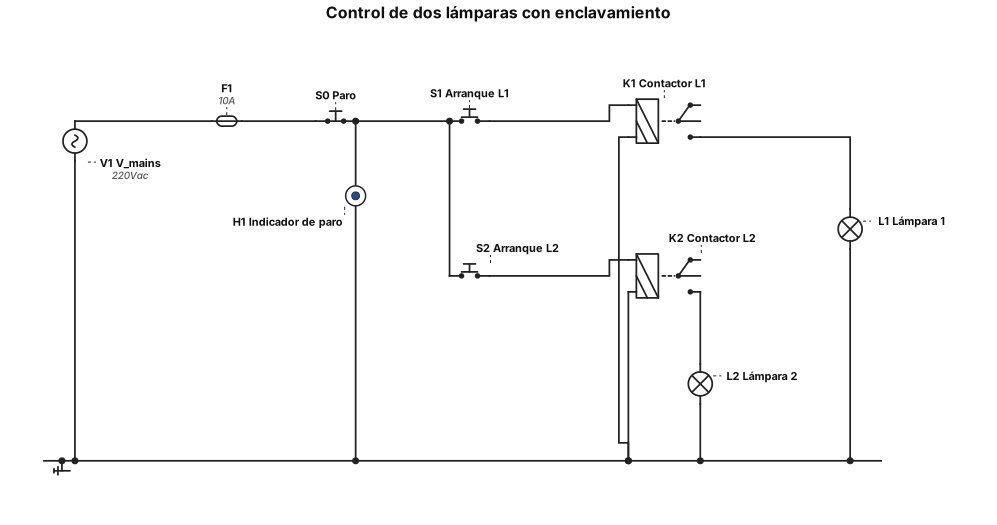
Se requiere hacer el diagrama de control de acuerdo a la siguienta solicitud. El encendido de dos lamparas, con las siguienta condiciones: tendra un solo boton de paro, 2 cada lampara tendra su boton de arranque, 3 cuando sea empora 1° Energizada la lampara 1, la lampara pa no podra-Ser enerdizada, Y la segunda lampara solo podra ser energizada si la primera se chergiza > con boton de paro. 5 si esta enerdizada la segunda lampara la primera no podia sar energizada 6. el paro también debe ser indicado
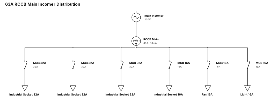
Create a clear single-line diagram with concise labels and the standard notation for this subject. 63aRCCB 30MA MAIN INCOMMER,32A 3 MCB OUT AND 16A 3 MCB OUT.ALL OUTPUTS ARE INDUSTRIAL SOCKET. ONE OUTPUT 16A FOR FAN AND ONE OUTPUT FOR LIGHTAND THIER NO BUS BAR
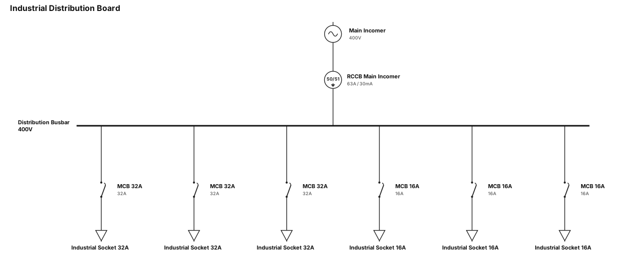
Create a clear single-line diagram with concise labels and the standard notation for this subject. 63aRCCB 30MA MAIN INCOMMER,32A 3 MCB OUT AND 16A 3 MCB OUT.ALL OUTPUTS ARE INDUSTRIAL SOCKET
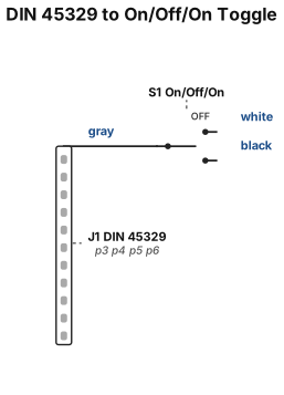
A circuit starting from a DIN 45329 connector. Pin 6 is attached via a white wire, pin 1 via a gray wire, pin 4 via a black wire. The wires terminate in 3-pin On/Off/On momentary toggle switch, white for center power signal, gray and black wires for the outer signal pins
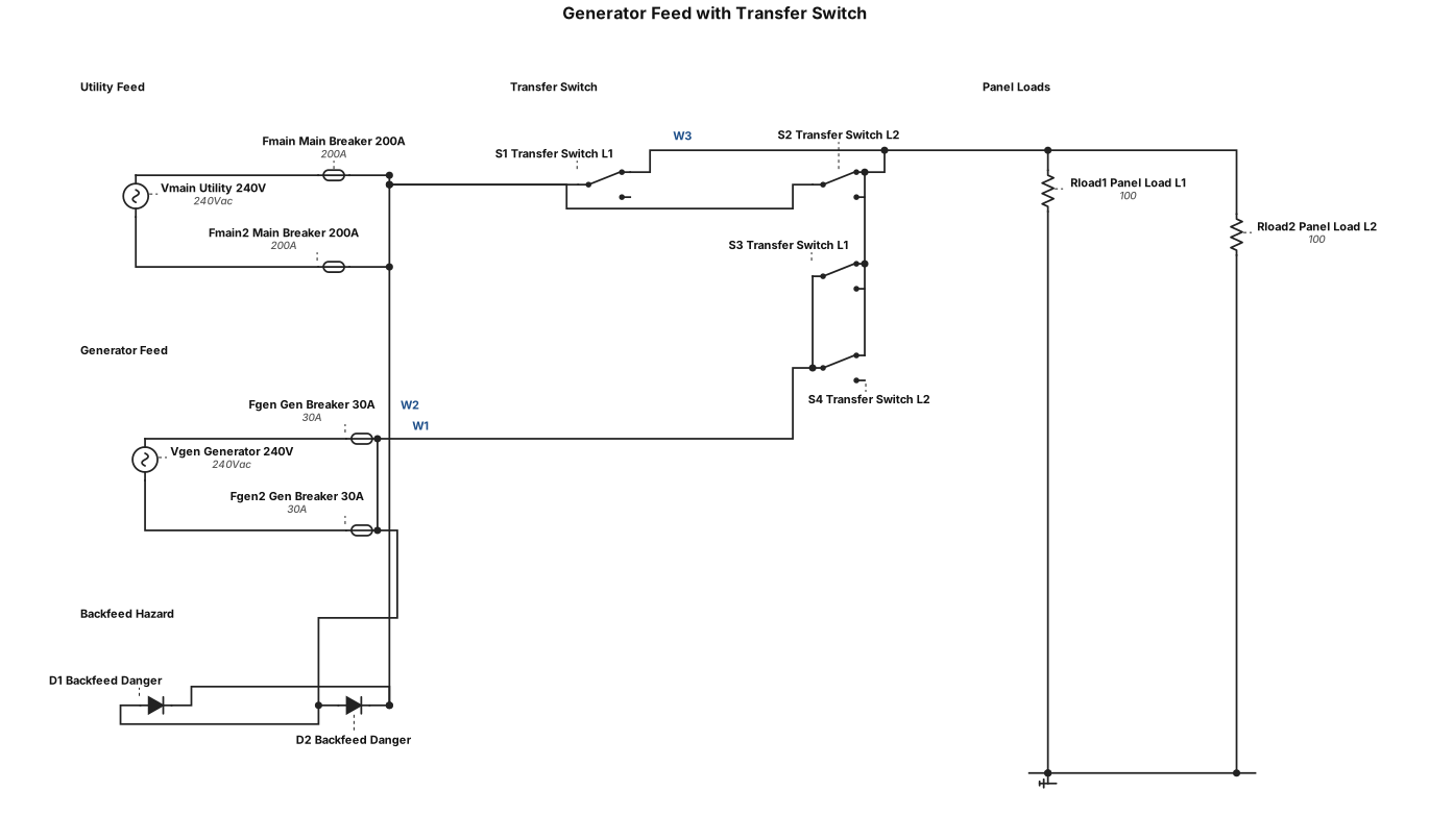
Generator feed off of breaker in panel with possible back feed showing possible dangers also it has a 200amp transfer switch make it a different style
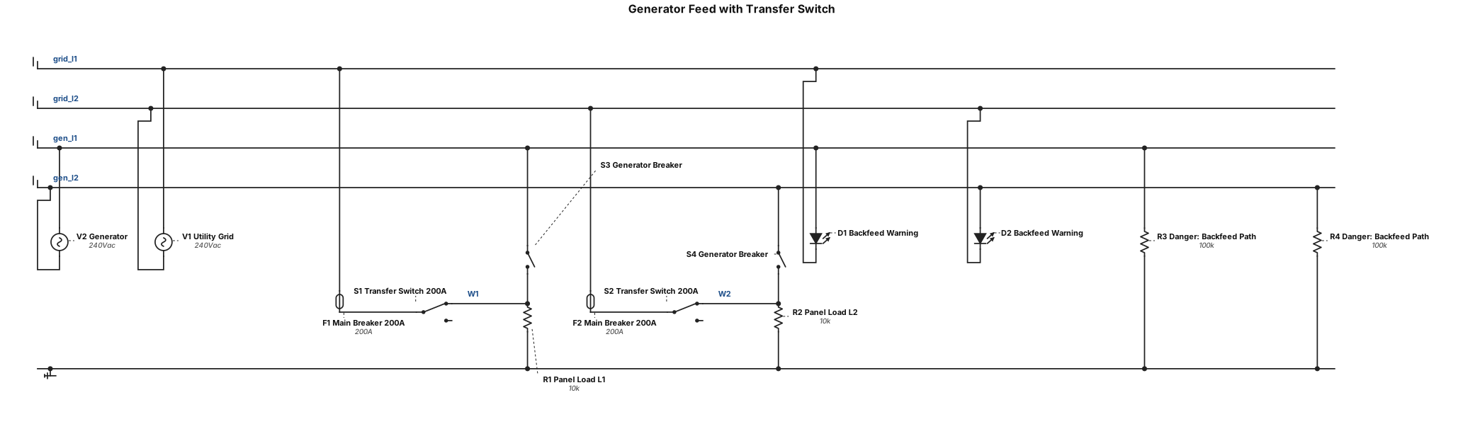
Generator feed off of breaker in panel with possible back feed showing possible dangers also it has a 200amp transfer switch
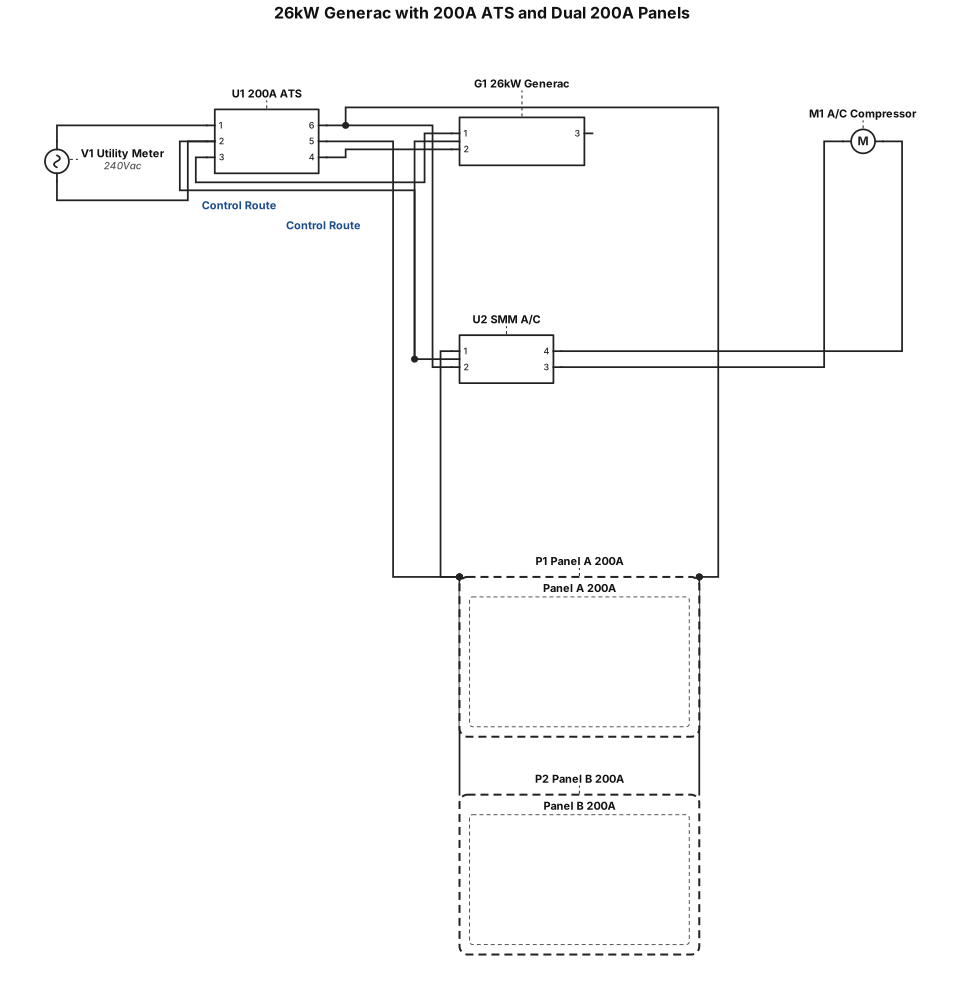
26kW Generac, 200A ATS, meter feed, split load to two 200A panels, SMM on A/C show the control wiring route too do not show the ground and neutrals or hots
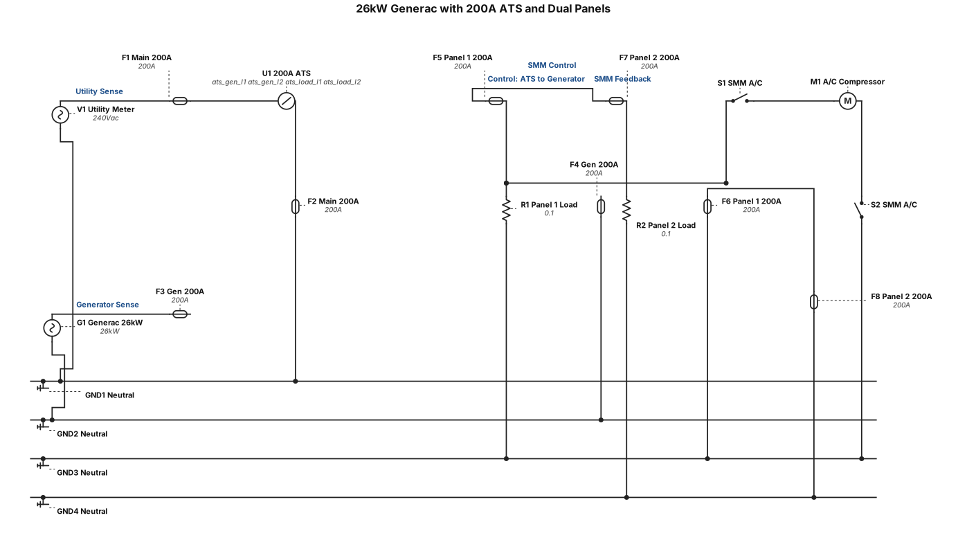
26kW Generac, 200A ATS, meter feed, split load to two 200A panels, SMM on A/C show the control wiring route too

Create a professional industrial P&ID schematic for a drainage sump system with two submersible pumps P1 (duty) and P2 (standby). Each pump has a DN40 vertical discharge pipe. Each discharge line contains: - pressure gauge PI - pressure transmitter PT, 4-20 mA - DN50 PN16 check valve CV1.1 / CV2.1 - DN50 PN16 isolation valve V1.1 / V2.1 Both discharge lines connect at the top to one common DN65 discharge header. Add a bypass around the check valve AND isolation valve on each pump line. Each bypass is pipe Ø13.5 x 1.6 mm, length 1200 mm, with ONE DN10 PN10 valve. Draw a rectangular sump containing both pumps. Show these horizontal water level lines and label ALL of them: - NIVEL MAXIM AVARIE - NIVEL MAXIM - PORNIRE POMPA REZERVA - PORNIRE POMPA LUCRU - OPRIRE POMPE Level instrumentation: - one float switch at NIVEL MAXIM AVARIE - two inductive level sensors side-by-side at the upper level - one float switch at OPRIRE POMPE - NO ultrasonic level transmitter Connect instrumentation signals with dashed lines to a control and automation panel. Use professional ISO/ISA P&ID symbols, black and white technical drawing, clean straight lines, equipment tags and Romanian labels.
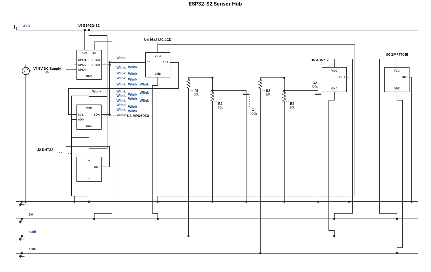
Draw a clean electronic schematic: standard symbols, black lines on white, no photos, no 3D. Use named net labels and power symbols for 3V3, 5V and GND instead of long wires. Print every pin name. Use only the parts listed, nothing else. PARTS U1 ESP32-S2 board, drawn as a block with pins: 3V3, 5V, GND, GPIO1, GPIO2, GPIO4, GPIO8, GPIO9 V1 5V DC supply (+5V and GND) U2 DHT22 module, pins: +, OUT, - U3 MPU6050 module, pins: VCC, GND, SCL, SDA, AD0 U4 16x2 I2C LCD, pins: GND, VCC, SDA, SCL U5 ACS712 module, low-voltage side only, pins: VCC, OUT, GND U6 ZMPT101B module, low-voltage side only, pins: VCC, OUT, GND R1 10k, R2 20k, C1 100nF (current divider) R3 10k, R4 20k, C2 100nF (voltage divider) CONNECTIONS Power: - V1 +5V -> U1 pin 5V. V1 - -> U1 pin GND. - U1 3V3 -> net 3V3. U1 5V -> net 5V. U1 GND -> net GND. - net 3V3 -> U2 "+" and U3 VCC. - net 5V -> U4 VCC, U5 VCC, U6 VCC. - net GND -> U2 "-", U3 GND, U3 AD0, U4 GND, U5 GND, U6 GND. Signals: - U1 GPIO4 -> U2 OUT. - U1 GPIO8 -> net SDA -> U3 SDA and U4 SDA. - U1 GPIO9 -> net SCL -> U3 SCL and U4 SCL. - Current: U5 OUT -> R1 -> node A. Node A -> U1 GPIO1. Node A -> R2 -> GND. Node A -> C1 -> GND. - Voltage: U6 OUT -> R3 -> node B. Node B -> U1 GPIO2. Node B -> R4 -> GND. Node B -> C2 -> GND. LAYOUT: U1 in the centre, V1 above it. U2, U3 and U4 on the left. U5, U6 and their dividers on the right.
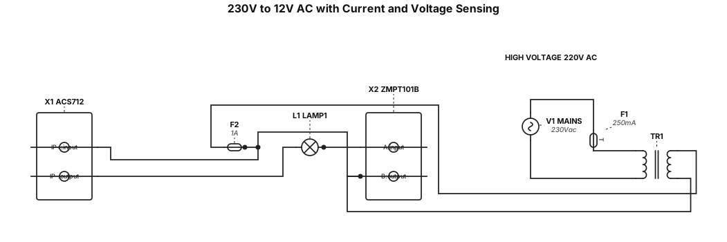
Draw a clean electrical schematic: standard symbols, black lines on white, no photos, no 3D. Print all labels. Use only the parts below. PARTS MAINS 230V AC source (terminals L and N) F1 fuse 250-500mA slow-blow TR1 transformer 230V to 12V: primary terminals I1 and I2, secondary terminals T1 and T2 F2 fuse 1A fast-blow X1 ACS712 current sensor, AC side only: a 2-terminal block with terminals IP+ and IP- LAMP1 12V AC lamp X2 ZMPT101B voltage sensor, AC side only: a 2-terminal block with terminals A and B CONNECTIONS Primary: MAINS L -> F1 -> TR1 I1. MAINS N -> TR1 I2. Secondary loop: TR1 T1 -> F2 -> X1 IP+. X1 IP- -> LAMP1 terminal 1. LAMP1 terminal 2 -> TR1 T2. Voltage sensor: X2 terminal A -> the wire between F2 and X1 IP+. X2 terminal B -> the wire between LAMP1 and T2. X1 is in SERIES with the lamp. X2 is in PARALLEL across the secondary. LAYOUT: left to right: MAINS, F1, TR1, then the secondary loop with the lamp at the far right. Draw a dashed box around MAINS, F1 and the primary side, labelled "HIGH VOLTAGE 220V AC". Add the note: "X1 and X2 output pins connect to the ESP32 circuit (separate schematic)". Draw no ground connections on this schematic.
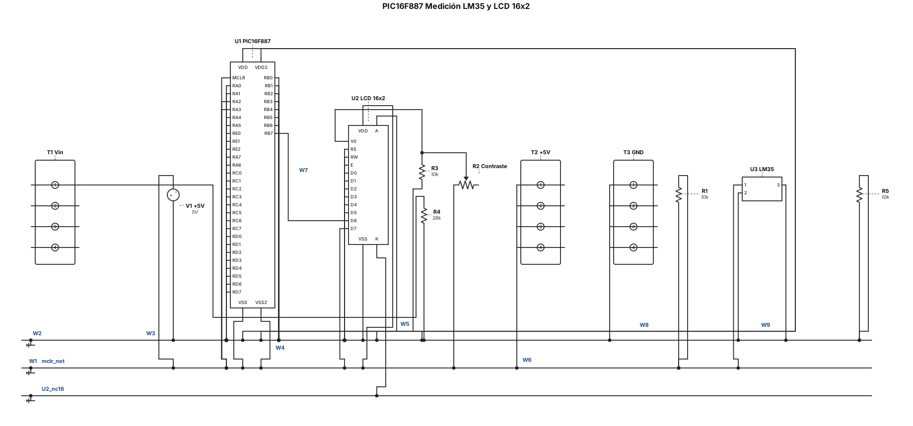
Genera un diagrama esquemático eléctrico completo y técnicamente correcto para un circuito de medición con PIC16F887 (DIP-40), sensor de temperatura LM35, divisor de voltaje y pantalla LCD 16x2. Conexiones obligatorias: - LM35: salida al pin RA0/AN0 del PIC, pin físico 2. - Divisor de voltaje: resistencia de 38 kΩ desde Vin hasta el punto medio y resistencia de 10 kΩ desde el punto medio hasta GND. El punto medio se conecta a RA1/AN1, pin físico 3. - LCD 16x2 en modo de 4 bits: - RS al RB0, pin 33. - E al RB1, pin 34. - D4 al RB4, pin 37. - D5 al RB5, pin 38. - D6 al RB6, pin 39. - D7 al RB7, pin 40. - RW a GND. - PIC: VDD, pines 11 y 32, a +5 V. - PIC: VSS, pines 12 y 31, a GND. - MCLR, pin 1, conectado a +5 V mediante una resistencia de 10 kΩ. - LCD: VDD a +5 V, VSS a GND y V0 al terminal central de un potenciómetro de 10 kΩ para contraste. - Todas las tierras deben estar conectadas en común. Utiliza los números reales de los pines del PIC16F887 DIP-40. No cambies las conexiones, no inventes componentes ni omitas terminales. Presenta un esquema eléctrico profesional, con símbolos normalizados, cables visibles y etiquetas legibles. Si no puedes representar alguna conexión correctamente, indícala como no resuelta en lugar de adivinar.
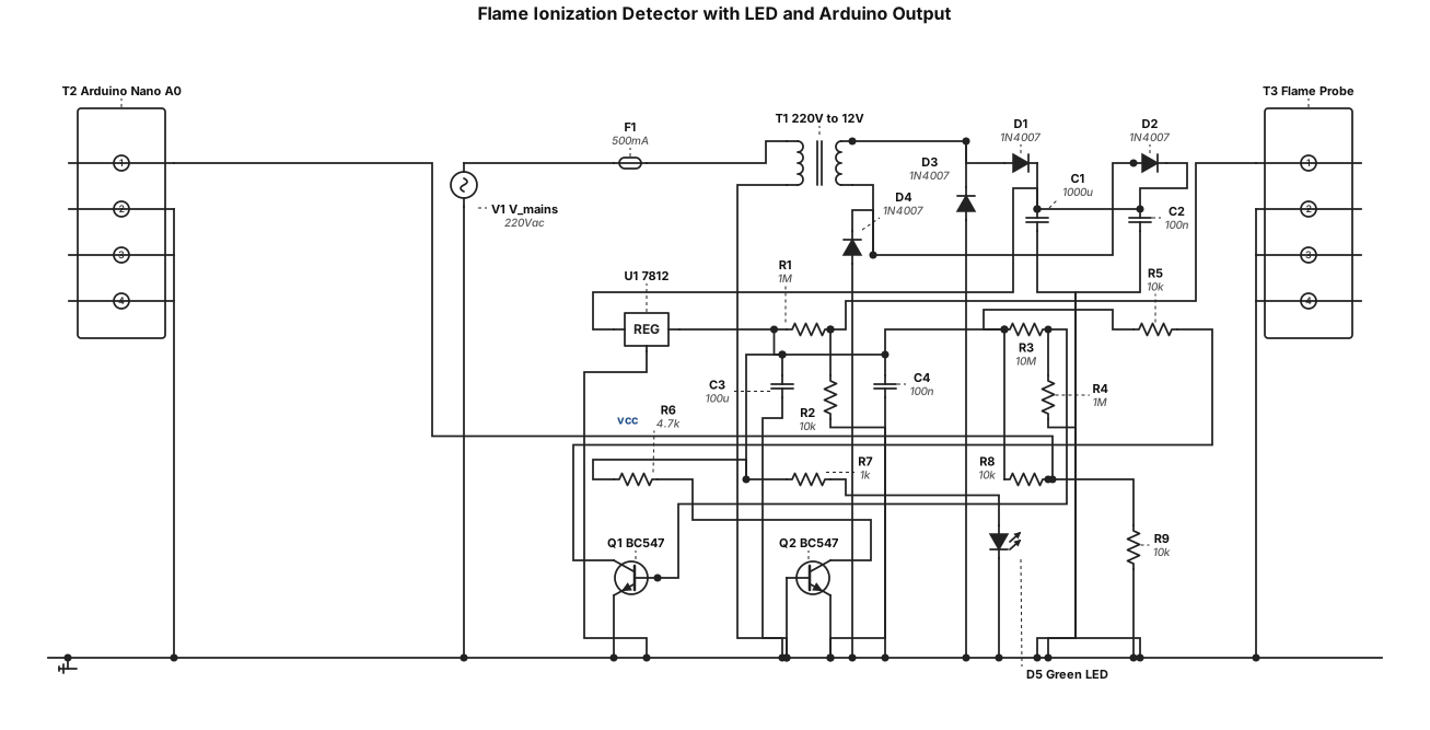
Design an electronic circuit that can be assembled at home using discrete components, which performs the following function: The circuit will detect the presence of a flame in a gas burner using the principle of flame ionization detection. When a flame is detected, it will turn on a green LED; when no flame/combustion is present, it will turn the LED off. Include a signal output so that the signal can be fed into an Arduino Nano in a subsequent stage. The circuit should be powered by the 220-volt AC residential mains supply, preferably using a traditional iron-core transformer. Provide the circuit design as a high-resolution image.
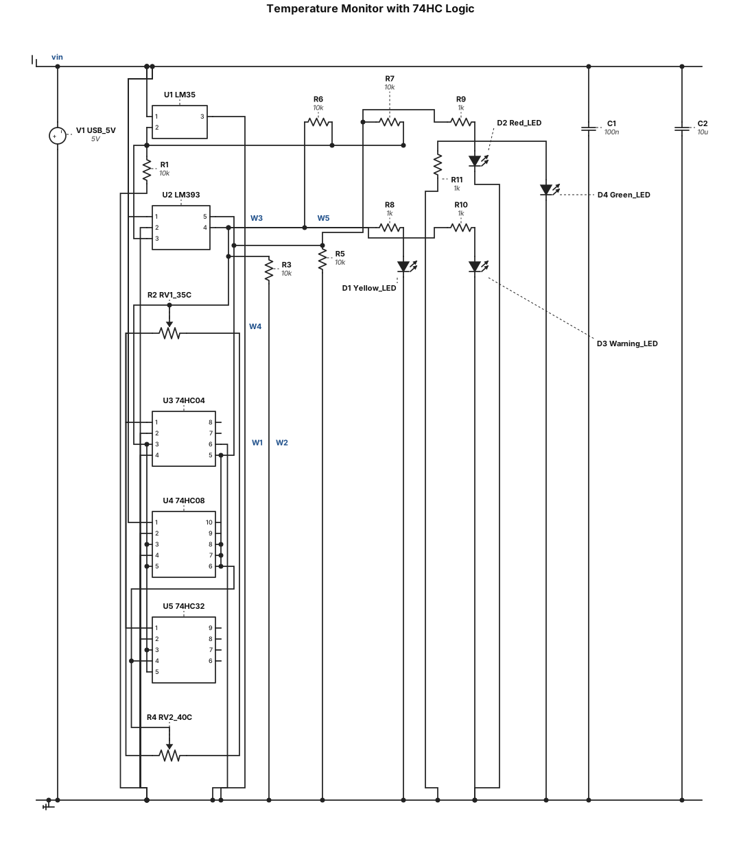
Modify the existing schematic. Do not redesign the project or replace the components. 1. Replace all generic logic blocks with actual 74HC04, 74HC08 and 74HC32 ICs. 2. Show actual DIP-14 pin numbers. 3. Use 74HC04: - Pin 1 = H35, pin 2 = NOT H35. - Pin 3 = H40, pin 4 = NOT H40. 4. Use 74HC08: - Pins 1 and 2 receive H35 and NOT H40; pin 3 drives Yellow LED. - Pins 4 and 5 both receive H40; pin 6 drives Red LED. 5. Use 74HC32: - Pins 1 and 2 receive H35 and H40; pin 3 drives Warning LED. 6. Connect Green LED to 74HC04 pin 2. 7. Connect every LED through its own 1 kΩ resistor. 8. Verify LM393 pin connections, both 10 kΩ output pull-up resistors and the two temperature reference potentiometers. 9. Show +5V on pin 14 and GND on pin 7 of every logic IC. 10. Ensure all LED outputs are controlled by their respective logic gates. Keep the LM35, LM393, potentiometers, four LEDs and USB 5V supply. Generate a complete electrical schematic with standard symbols, visible IC pin numbers and no floating inputs.