
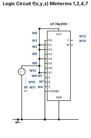
a logic circuit that implement f(x,y,z) with minterms 1,2,4,7 using ic 74ls151
ENGINEERING DRAWING ARCHIVE · REAL SPECS
Engineering Diagram Examples from Real Specifications
Browse eligible circuit, ladder, single-line, P&ID, breadboard, timing, and logic drawings with their original prompts.
Browse 540 real creationsCOMMUNITY OUTPUTS · EXACT PROMPTS
Main engineering studio
Showing 97–120 of 380. No stock examples or system defaults. Choose a tool, study a real result, then reopen its prompt as your starting point.
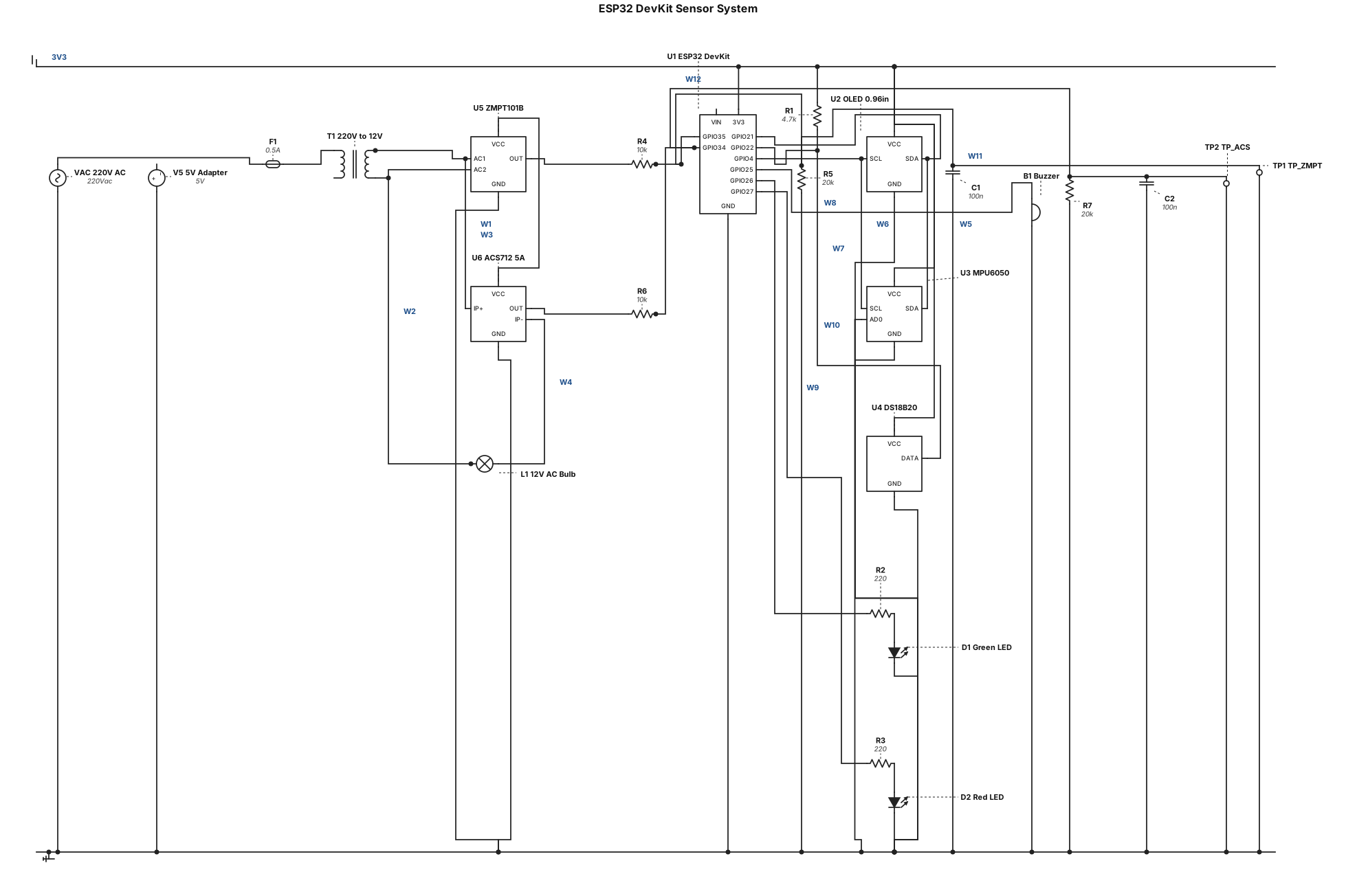
An ESP32 DevKit circuit powered from a 5 V adapter on VIN and GND, with the 3V3 pin supplying the 3.3 V parts. Connect a 0.96 inch I2C OLED display (VCC to 3V3, GND to GND, SDA to GPIO21, SCL to GPIO22) and an MPU6050 on the same I2C bus (VCC to 3V3, GND and AD0 to GND, SDA to GPIO21, SCL to GPIO22). Add a DS18B20 temperature sensor (VCC to 3V3, GND to GND, DATA to GPIO4) with a 4.7k pull-up resistor between DATA and 3V3. Add a buzzer on GPIO25, a green LED on GPIO26 and a red LED on GPIO27, each with a 220 ohm series resistor to GND. Add a ZMPT101B voltage sensor module (VCC to 5V, GND to GND, OUT to GPIO35) and an ACS712 5A current sensor module (VCC to 5V, GND to GND, OUT to GPIO34). Each analog OUT goes through a 10k/20k resistor divider (10k in series from OUT, 20k to GND at the GPIO node) with a 100nF capacitor from the GPIO pin to GND. Add a 220 V AC source feeding a 0.5 A fuse and then the primary of a 220 V to 12 V mini transformer. Connect the ZMPT101B AC input across the transformer secondary. Wire one secondary terminal through the ACS712 IP+ and IP- terminals in series, then to a 12 V AC bulb, and return the other secondary terminal directly to the bulb. Label all GPIO pins and add test points on the two analog sensor outputs.
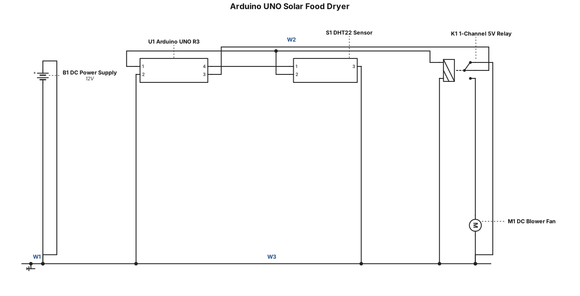
Create a technically accurate circuit wiring diagram for an Arduino UNO based Solar Food Dryer prototype. Components: - Arduino UNO R3 - DHT22 temperature and humidity sensor - 1-channel 5V relay module - DC blower fan - DC battery/power supply - Breadboard - Jumper wires Connections: - DHT22 VCC → Arduino 5V - DHT22 GND → Arduino GND - DHT22 DATA → Arduino digital pin D2 - Relay VCC → Arduino 5V - Relay GND → Arduino GND - Relay IN → Arduino digital pin D8 - Use the relay to switch the DC blower fan. - Show the separate power connection for the blower fan through the relay. - Clearly show positive (+) and negative (−) power lines. - Clearly label every component, pin, wire, and connection. - Use standard electronic schematic symbols. - Make the diagram clean, realistic, and suitable for a first-year engineering college project. - Do not add any components that are not listed. - Do not include a servo motor, gas sensor, heater, LCD, or Wi-Fi module.
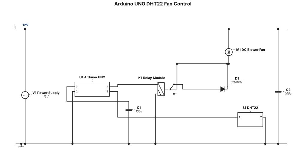
Arduino UNO DHT22 DC blower fan Relay module Power supply/battery Breadboard Jumper wires
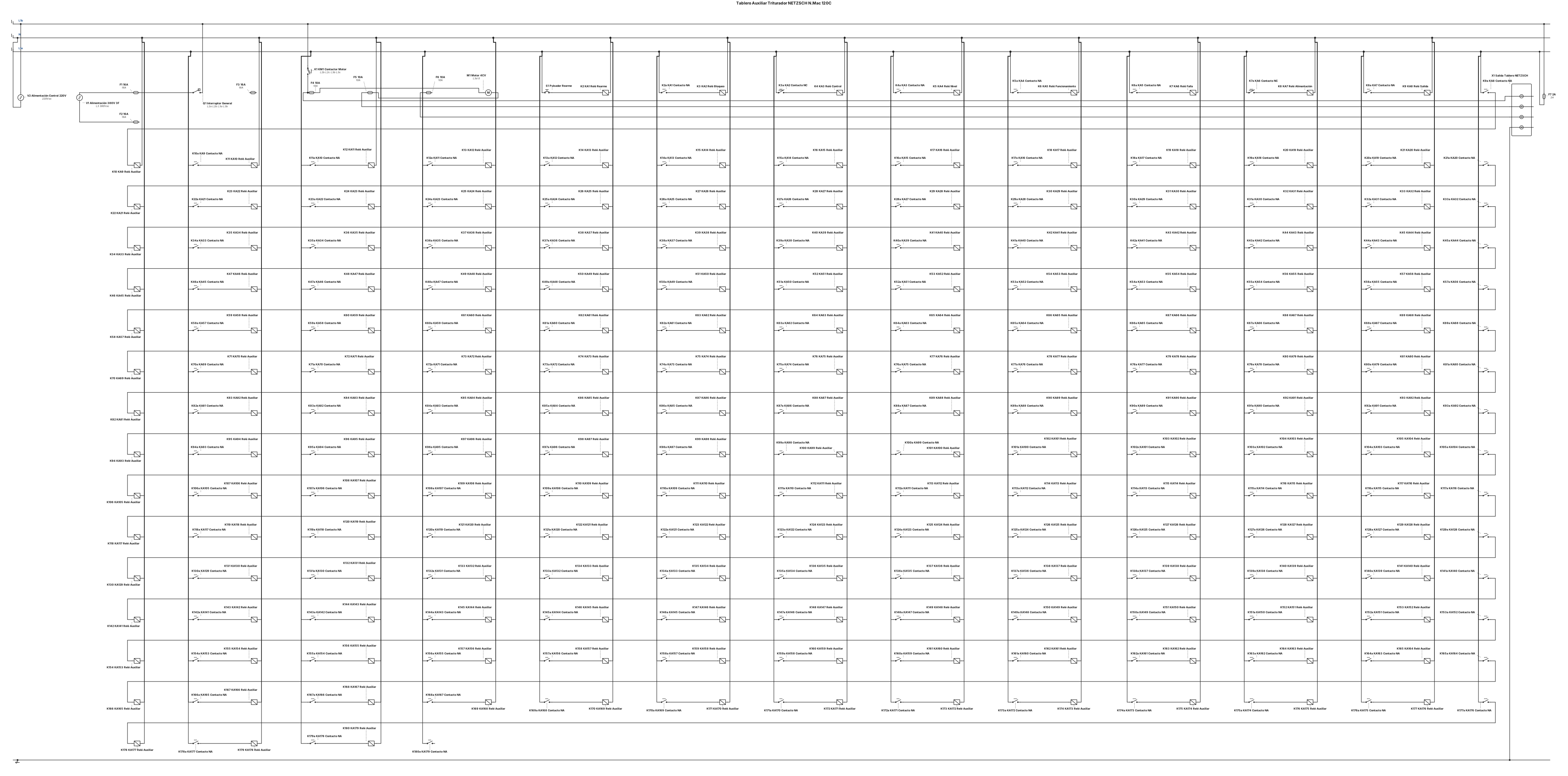
Diseña un **plano eléctrico industrial profesional con simbología IEC** para un tablero auxiliar de alimentación y control de un triturador NETZSCH N.Mac 120C. **Potencia:** alimentación 380 V trifásicos, motor 4 CV, interruptor general, protecciones y salida al tablero original NETZSCH. **Control:** fuente 220 VCA/24 VCC (alimentación de 220 V por confirmar), radar de nivel 4–20 mA, display digital, relés auxiliares y pulsador de rearme. **Señalización:** pilotos de alimentación, funcionamiento y falla por nivel alto. **Funcionamiento:** arranque a 10 cm, parada por debajo de 10 cm y bloqueo a 60 cm, con corte de alimentación al motor y rearme manual. El tablero original NETZSCH ya contiene los contactores de inversión y el PLC. **Dibujar únicamente los circuitos eléctricos de potencia, control y señalización**, incluyendo contactos NA/NC, bobinas, protecciones, borneras y numeración de cables. No incluir programación, diagramas de PLC ni diagramas de bloques. Formato A3 horizontal, PDF y archivo CAD editable. Identificar las conexiones pendientes de verificar.
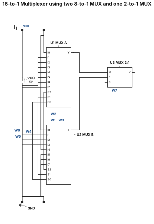
Create a highly accurate, professional digital logic circuit schematic on a pure white background. **Title:** Implementation of a 16-to-1 Multiplexer using two 8-to-1 Multiplexers and one 2-to-1 Multiplexer. **Architecture:** 1. Two 8-to-1 multiplexers: - MUX A handles data inputs I0 to I7. - MUX B handles data inputs I8 to I15. - Both multiplexers share three selection signals: - b → S2 - c → S1 - d → S0 2. Data input connections: - MUX A: I0 = 1 (VCC), all other inputs I1–I7 = 0 (GND). - MUX B: local input I0 = 1 (global I8), local input I4 = 1 (global I12), all other inputs = 0 (GND). 3. Final selection stage: - Connect output YA of MUX A to input I0 of a 2-to-1 MUX. - Connect output YB of MUX B to input I1 of the 2-to-1 MUX. - Connect variable a to the select input S of the 2-to-1 MUX. - Final output is F. **Mathematical expression:** F = NOT(a) × YA + a × YB **Visual requirements:** - Clearly show all three multiplexers. - Use correct standard MUX symbols. - Draw all connections without crossing wires unnecessarily. - Label every data input, selection input and output. - Use different colors for a, b, c and d. - Show VCC (logic 1) and GND (logic 0). - Use clean orthogonal wiring, professional university-level engineering notation. - Make the diagram landscape, high resolution, readable and suitable for an engineering examination report. - Do not add incorrect gates, extra inputs or extra multiplexers. - Ensure all connections are electrically and logically correct.
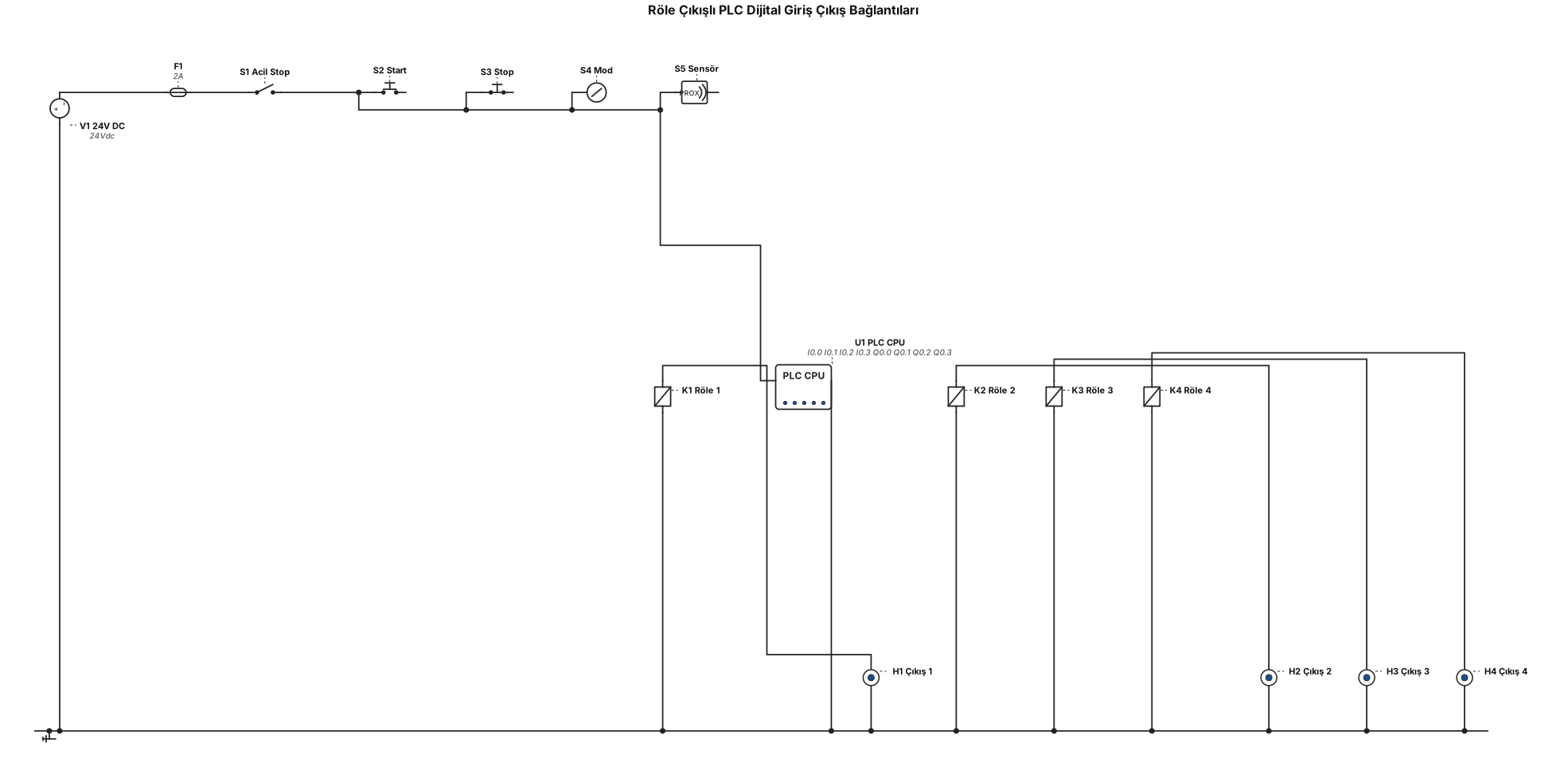
röle çıkışlı plc dijital giriş çıkış bağlantıları (cadesımu v4 program tabaı ustunde)
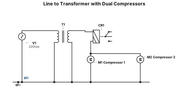
From line to transformer, line to CR 1 to compressor then parallel with another compressor, and back to neutral
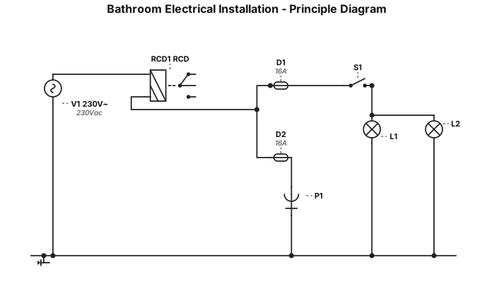
Create a clear and professional electrical principle diagram (schéma de principe) for a bathroom electrical installation, following these requirements: 1. One bipolar switch S1 controls two lamps, L1 and L2, simultaneously. 2. The two lamps must be connected in parallel. 3. One socket outlet P1 is powered directly, without passing through the switch. 4. Circuit breaker D1 protects the lighting circuit. 5. Circuit breaker D2 protects the socket circuit. 6. One RCD (residual current device / differential switch) protects the entire installation and is installed upstream of both circuit breakers. Drawing requirements: * Use only standard electrical symbols, as in an electrician’s school exercise. * Draw a real electrical principle diagram, not a realistic illustration. * Use these wire colors: phase = red, neutral = blue, protective earth = green/yellow. * Show every conductor and connection clearly. * Label all components: RCD, D1, D2, S1, L1, L2 and P1. * Make the diagram simple, clean, readable, and avoid unnecessary wire crossings. * Follow Belgian electrical installation standards (RGIE). Do not create a wiring diagram or a layout diagram. I only want the electrical principle diagram.
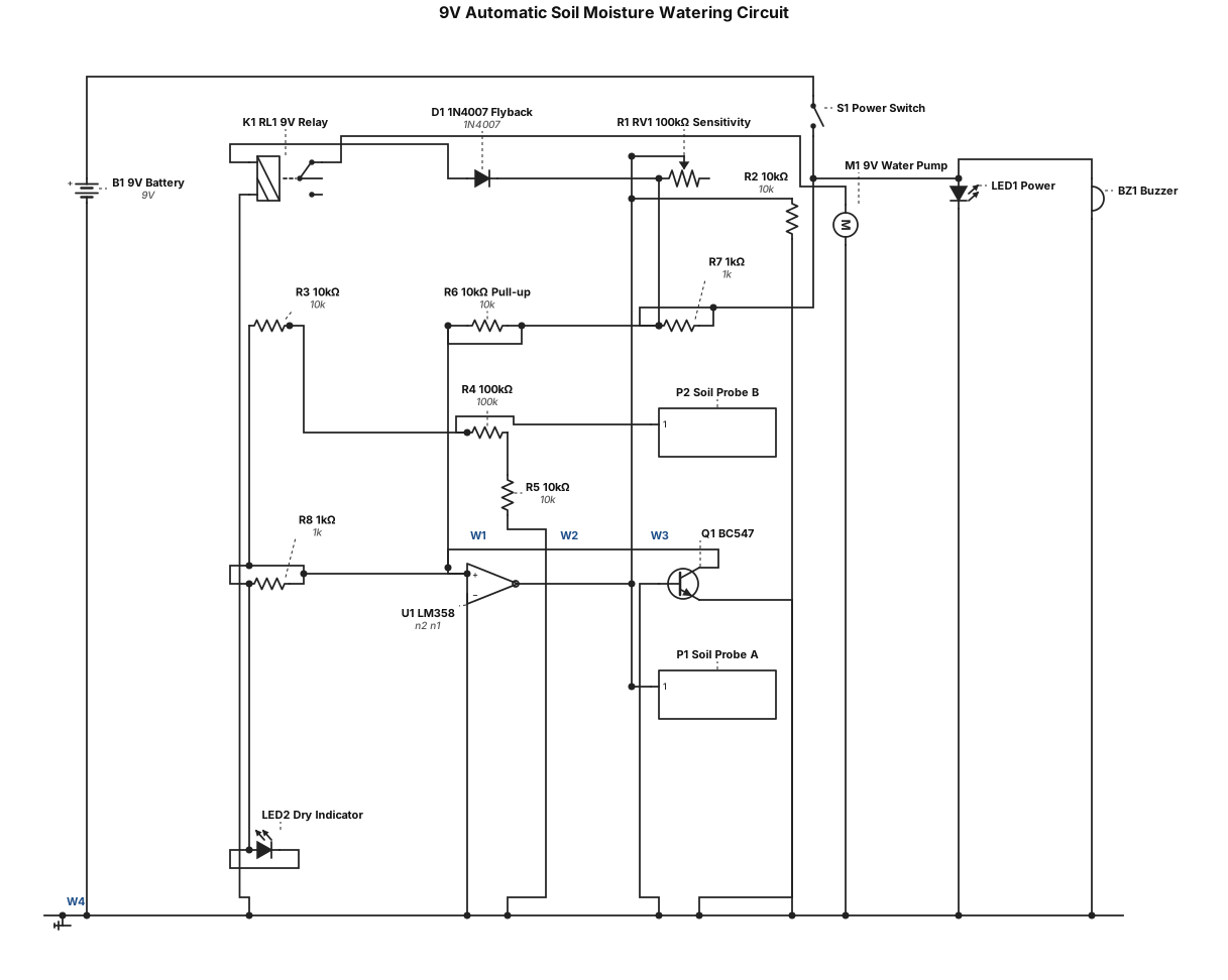
Draw a complete 9V automatic soil moisture watering circuit using LM358, BC547, 100kΩ potentiometer, resistors, 9V relay, 1N4007 diode, 1 LEDs, buzzer, two soil probes and a 9V water pump. Show all component symbols, pin numbers, values and exact wire connections. The pump should turn ON when soil is dry and OFF when soil is wet. Make the schematic neat and easy to understand.
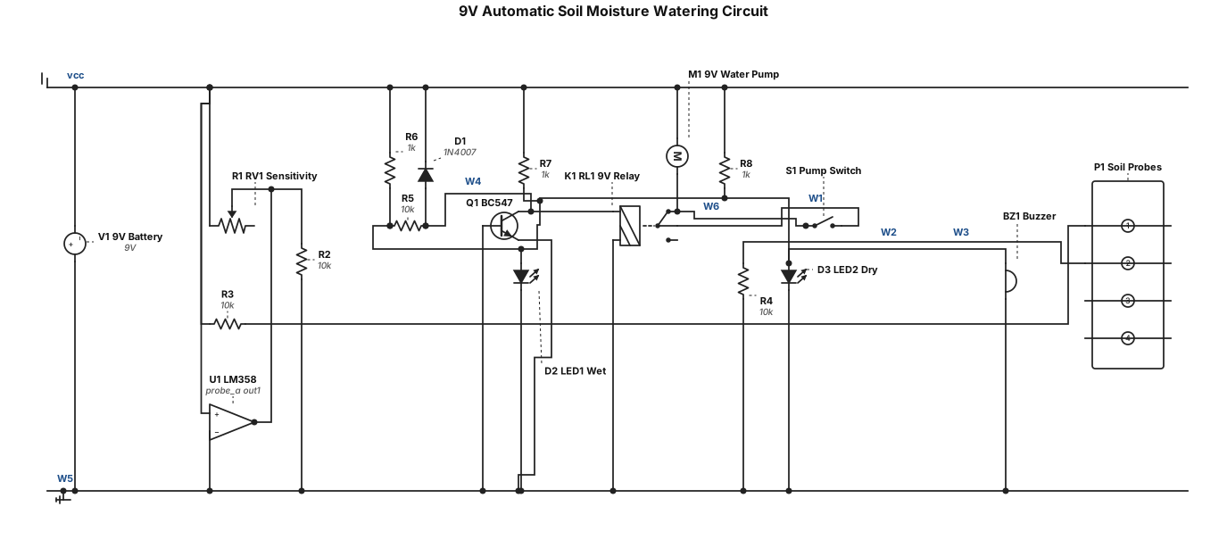
Draw a complete 9V automatic soil moisture watering circuit using LM358, BC547, 100kΩ potentiometer, resistors, 9V relay, 1N4007 diode, LEDs, buzzer, two soil probes and a 9V water pump. Show all component symbols, pin numbers, values and exact wire connections. The pump should turn ON when soil is dry and OFF when soil is wet. Make the schematic neat and easy to understand.
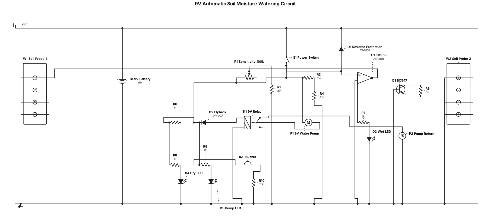
Draw a complete 9V automatic soil moisture watering circuit using LM358, BC547, 100kΩ potentiometer, resistors, 9V relay, 1N4007 diode, 3 LEDs, buzzer, two soil probes and a 9V water pump. Show all component symbols, pin numbers, values and exact wire connections. The pump should turn ON when soil is dry and OFF when soil is wet. Make the schematic neat and easy to understand.
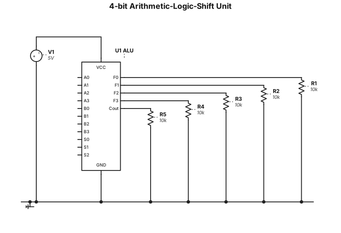
Design and implement 4-bit arithmetic-logic-shift unit.
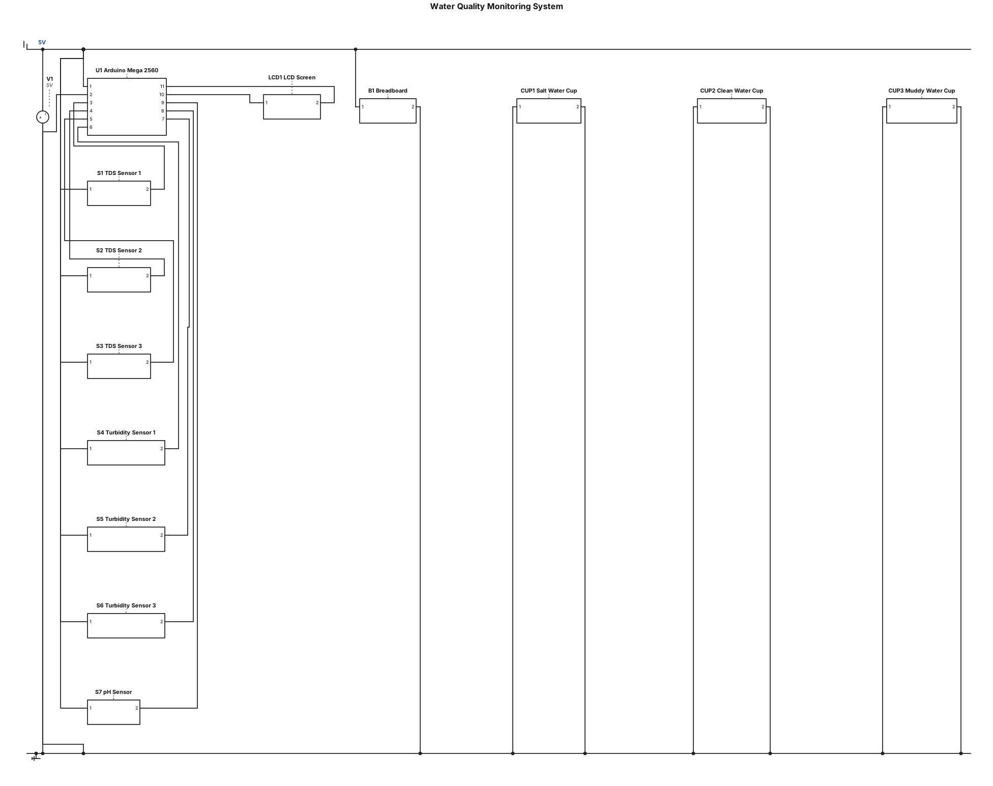
Create a simple water quality circuit using Arduino Mega 2560, three TDS sensors, three turbidity sensors, one pH sensor, and one LCD screen. Connect the TDS sensors to A0, A1, A2, the turbidity sensors to A3, A4, A5, and the pH sensor to A6. Connect the LCD screen to pins 20 and 21. Use a 5V power supply and a common GND for all compatible components. Include a breadboard and three water cups with salt water, clean water, and muddy water.
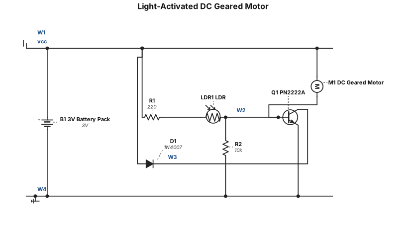
Create a breadboard wiring diagram for a light-activated DC geared motor using one PN2222A NPN transistor, one LDR, a 220-ohm resistor, a 10k-ohm resistor, a 1N4007 flyback diode, and a 3V battery pack. The motor should turn on in bright light and turn off in darkness. Show exact breadboard hole positions and verify all electrical connections. Use a horizontal breadboard with the center gap running left to right. Do not assume a transistor pinout without checking its datasheet.
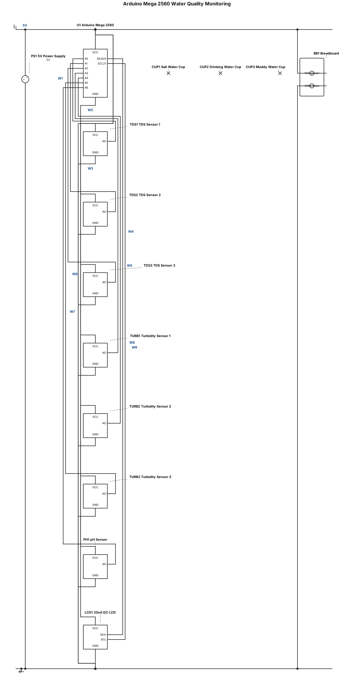
Draw a complete Arduino Mega 2560 water quality monitoring circuit with 3 TDS sensors, 3 turbidity sensors, 1 pH sensor, and a 20x4 I2C LCD. Connect TDS sensors to A0, A1, A2, turbidity sensors to A3, A4, A5, and the pH sensor to A6. Connect LCD SDA to Arduino pin 20 and SCL to pin 21, with VCC and GND connected correctly. Use a 5V power supply, common GND, and the correct voltage for each sensor module. Include a breadboard, all wires, and 3 water cups containing salt water, drinking water, and muddy water.
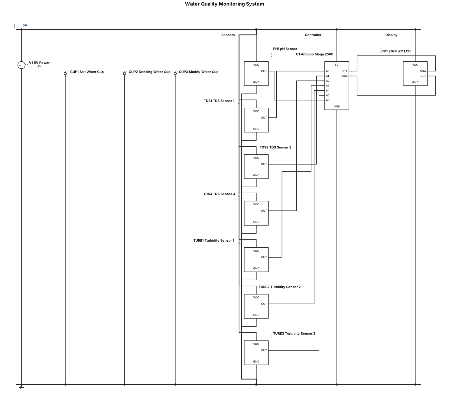
Draw a complete water quality monitoring circuit using Arduino Mega 2560, 3 TDS sensors, 3 turbidity sensors, 1 pH sensor, and a 20x4 I2C LCD. Connect TDS sensors to A0, A1, A2, turbidity sensors to A3, A4, A5, and pH to A6. Connect LCD SDA to pin 20 and SCL to pin 21, with correct power and ground connections. Use a 5V power source, common GND, and suitable operating voltage for each sensor module. Show a breadboard, all jumper wires, and 3 water cups containing salt water, drinking water, and muddy water.
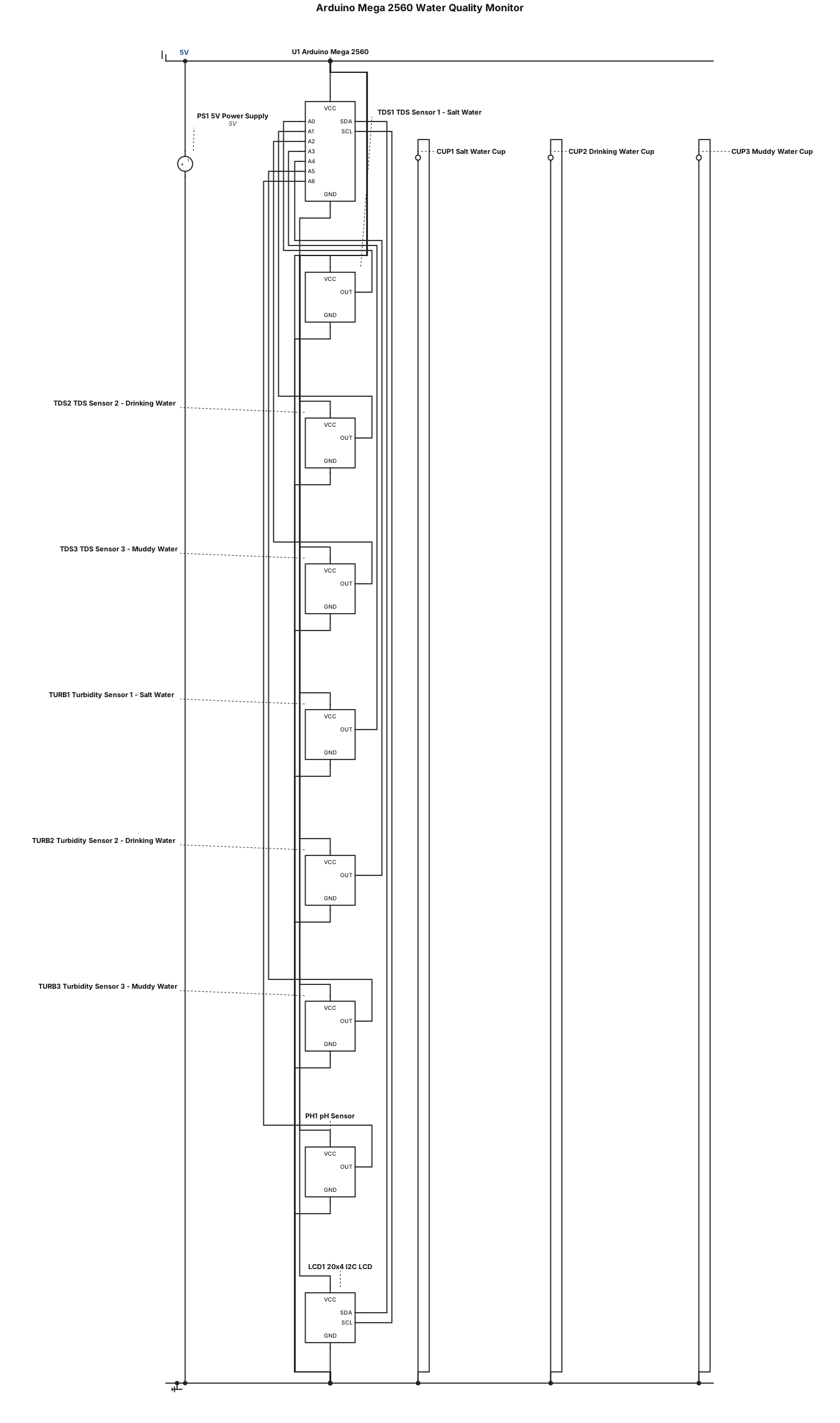
Draw a complete Arduino Mega 2560 water quality circuit with 3 TDS sensors, 3 turbidity sensors, 1 pH sensor, and a 20x4 I2C LCD. Connect all seven sensor outputs to Arduino pins A0 through A6, one sensor per pin. Connect the LCD SDA to pin 20 and SCL to pin 21. Use a 5V power supply, correct sensor voltages, and common GND for all components. Show a real breadboard with wires and 3 water cups: salt water, drinking water, and muddy water.
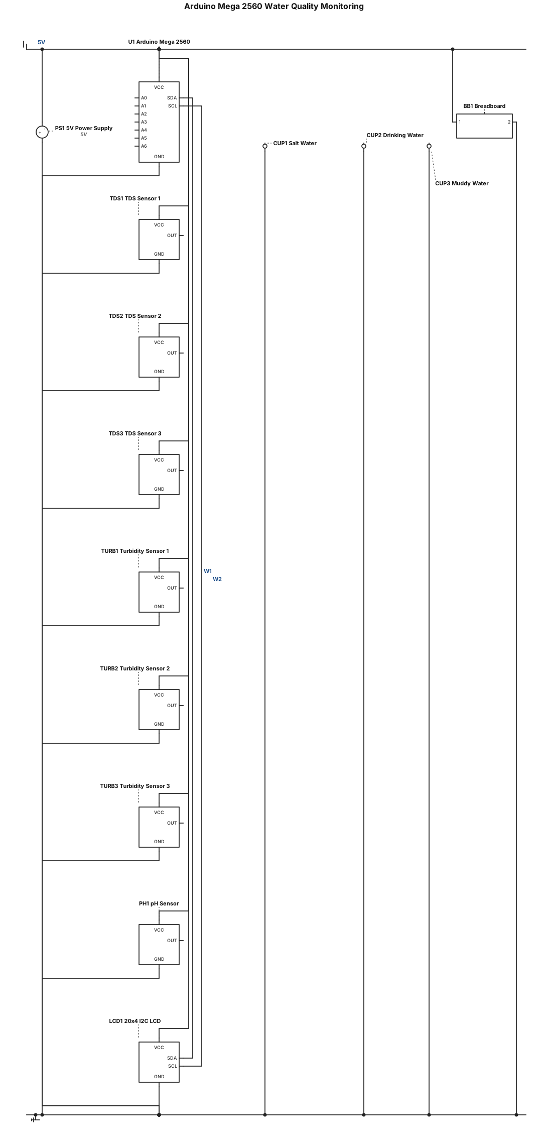
Draw a simple wiring diagram using Arduino Mega 2560, 3 TDS sensors, 3 turbidity sensors, 1 pH sensor, and a 20x4 I2C LCD. Connect the TDS sensors to A0, A1, A2, the turbidity sensors to A3, A4, A5, and the pH sensor to A6. Connect the LCD SDA to pin 20 and SCL to pin 21. Use a 5V power supply and connect all components to a common GND, using the correct voltage for each sensor. Include a breadboard and 3 water cups containing salt water, drinking water, and muddy water. Show all wires and connections clearly.
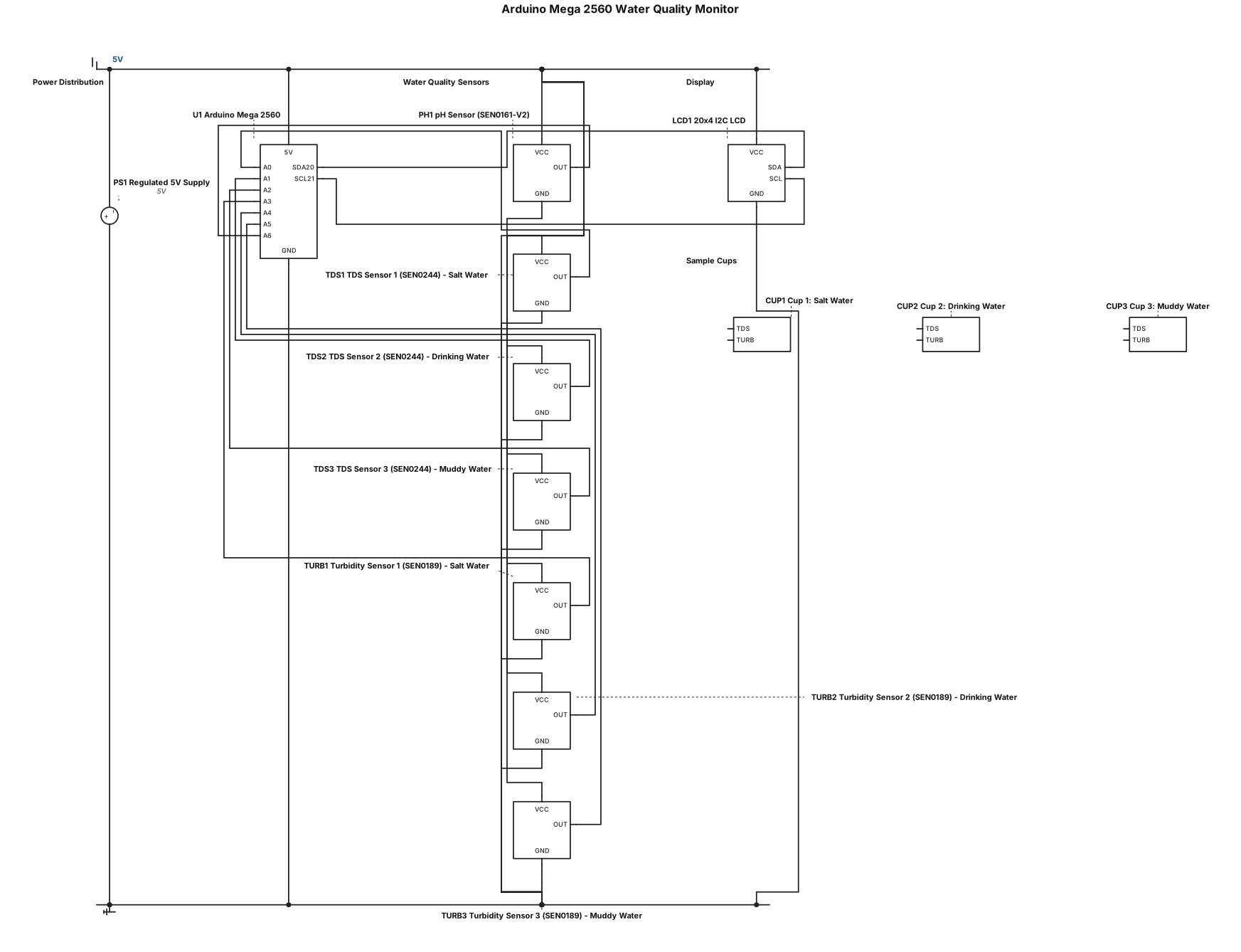
Create a realistic breadboard wiring diagram using Arduino Mega 2560, 3 TDS sensors (SEN0244), 3 turbidity sensors (SEN0189), 1 pH sensor (SEN0161-V2), and a 20x4 I2C LCD. Connect TDS sensors to A0–A2, turbidity sensors to A3–A5, pH to A6, and LCD SDA/SCL to pins 20/21. Use a regulated 5V power supply, common GND, and the correct operating voltage for each sensor module. Include 3 transparent cups containing salt water, drinking water, and muddy water, with one TDS and one turbidity sensor in each cup. Show the real breadboard, sensor modules, colored jumper wires, exact pin connections, and complete power and ground wiring.
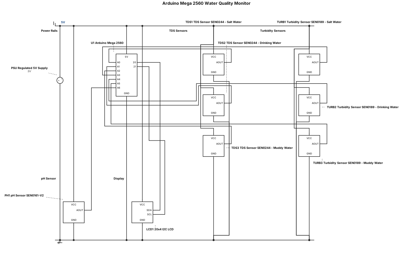
Create a realistic breadboard wiring diagram using Arduino Mega 2560, 3 TDS sensors (SEN0244), 3 turbidity sensors (SEN0189), 1 pH sensor (SEN0161-V2), and a 20x4 I2C LCD. Connect TDS sensors to A0–A2, turbidity sensors to A3–A5, pH to A6, and LCD SDA/SCL to pins 20/21. Use a regulated 5V power supply with common GND, and connect each module to its correct operating voltage. Include 3 transparent water cups: salt water, drinking water, and muddy water, with one TDS and one turbidity sensor in each cup. Show a real breadboard, all sensor modules, colored jumper wires, exact pin connections, and clearly labeled power rails. Make the circuit electrically correct and physically buildable.
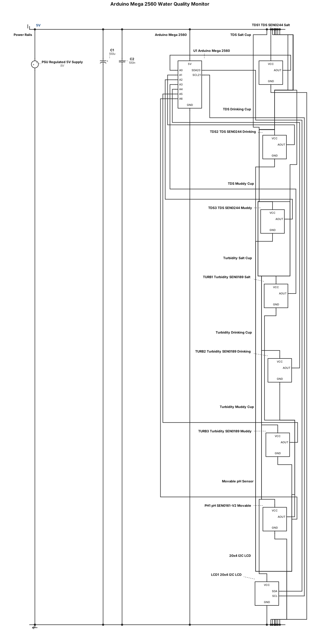
Create a realistic breadboard wiring diagram using Arduino Mega 2560, 3 TDS sensors (SEN0244), 3 turbidity sensors (SEN0189), 1 pH sensor (SEN0161-V2), and a 20x4 I2C LCD. Connect TDS sensors to A0–A2, turbidity sensors to A3–A5, pH to A6, and LCD SDA/SCL to pins 20/21. Use a regulated 5V power supply with common GND, correct sensor operating voltages, and clearly connected positive and negative breadboard rails. Include 3 water cups (salt, drinking, muddy), each with one TDS and one turbidity sensor, and one movable pH sensor. Show realistic components, sensor interface boards, all jumper wires, exact breadboard holes, and correct electrical connections.
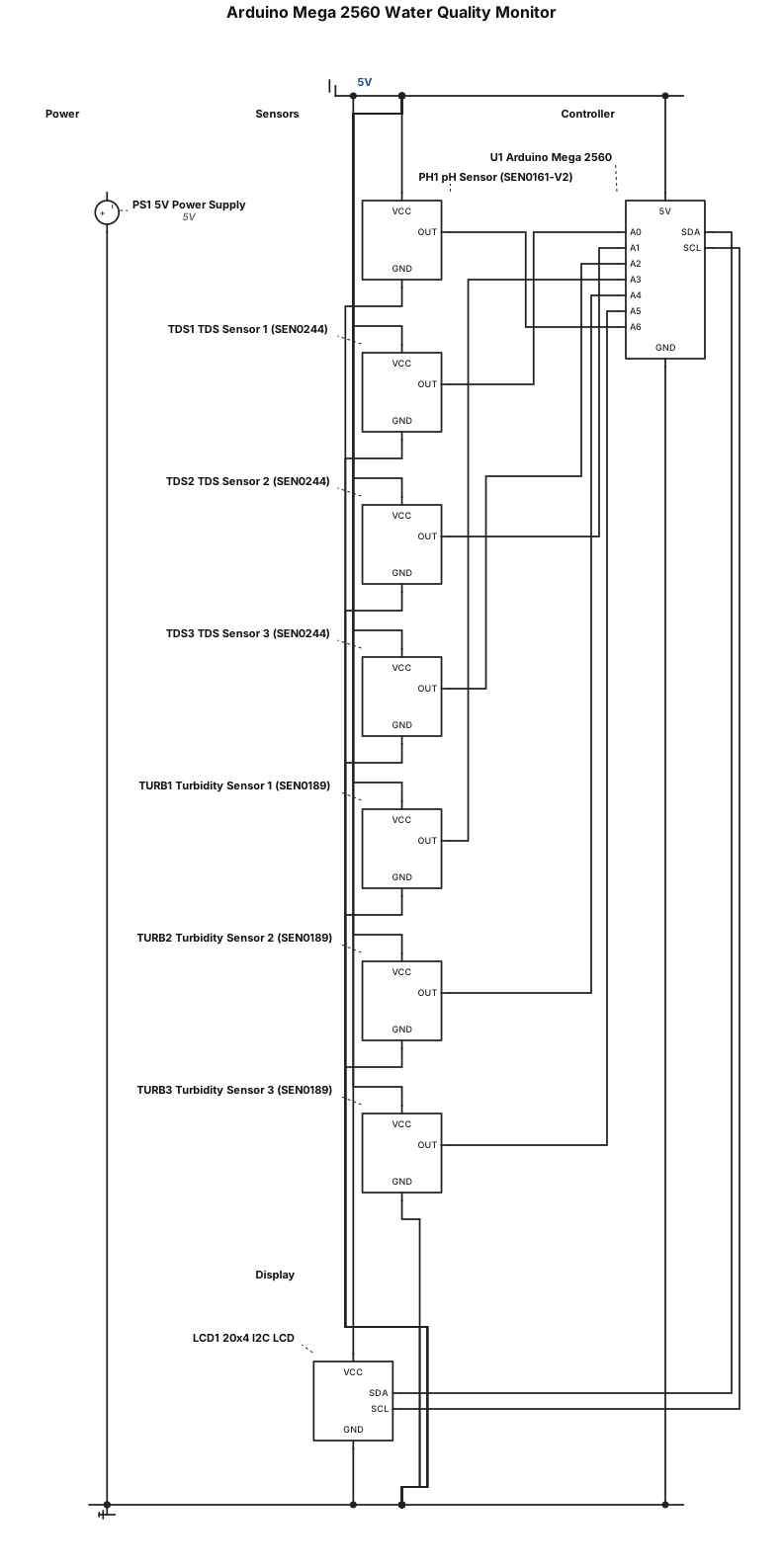
Create a complete, realistic breadboard wiring diagram using Arduino Mega 2560, 3 TDS sensors (SEN0244), 3 turbidity sensors (SEN0189), 1 pH sensor (SEN0161-V2), and a 20x4 I2C LCD. Connect TDS sensors to A0, A1, A2, turbidity sensors to A3, A4, A5, and the pH sensor to A6. Connect LCD SDA to pin 20 and SCL to pin 21. Use a suitable 5V power supply with clearly connected VCC and common GND for all compatible modules, and show every wire on a breadboard. Include 3 transparent cups: salt water, drinking water, and muddy water, each containing one TDS sensor and one turbidity sensor. The pH sensor is movable between cups. Show all real sensor modules, correct pin labels, and exact connections. Do not add unnecessary resistors or components. Make the diagram electrically accurate and ready for physical assembly.
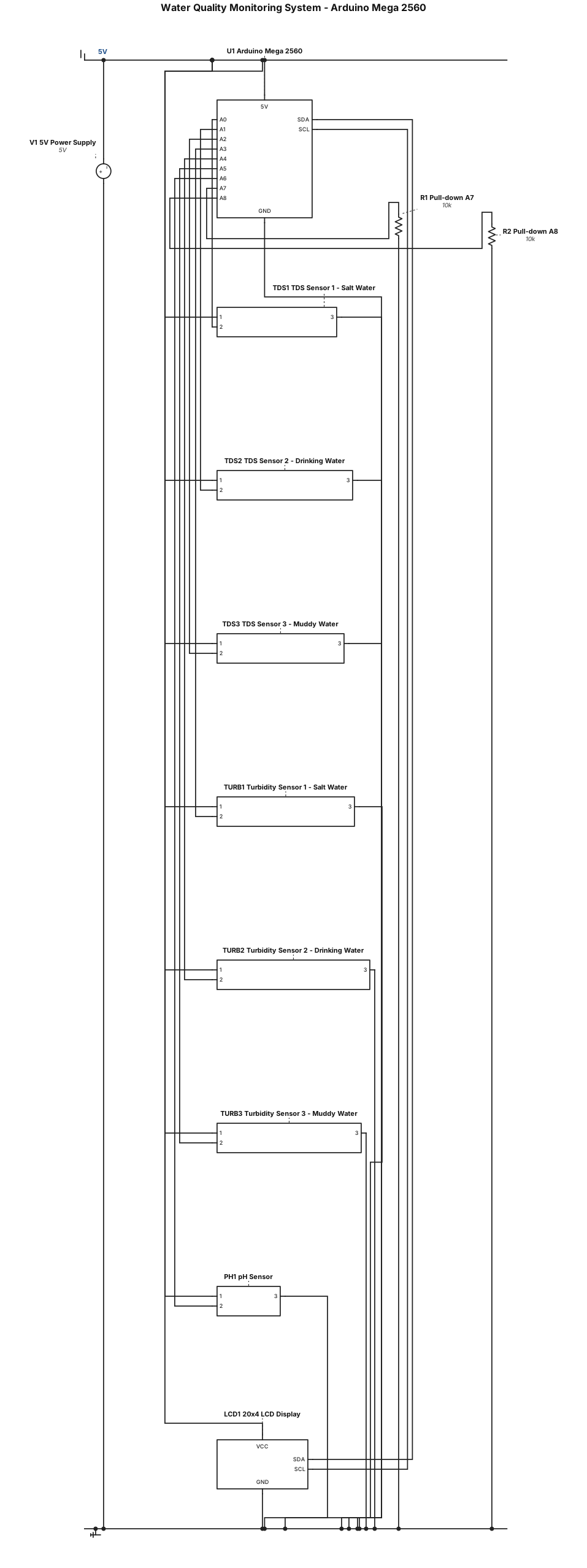
Create a complete wiring diagram for a water quality monitoring system using Arduino Mega 2560, 3 TDS sensors, 3 turbidity sensors, 1 pH sensor, and a 20x4 LCD screen. Connect all sensors and the LCD to the Arduino using a breadboard and jumper wires. The system uses a 5V power supply and has 3 water cups: salt water, drinking water, and muddy water. Please correct the wiring diagram and make sure all components are properly connected to 5V and GND. Show the positive and negative power connections, all sensor signal wires, and the Arduino Mega 2560 pin numbers. Include a breadboard and make sure the entire circuit is electrically correct and ready for real assembly.