
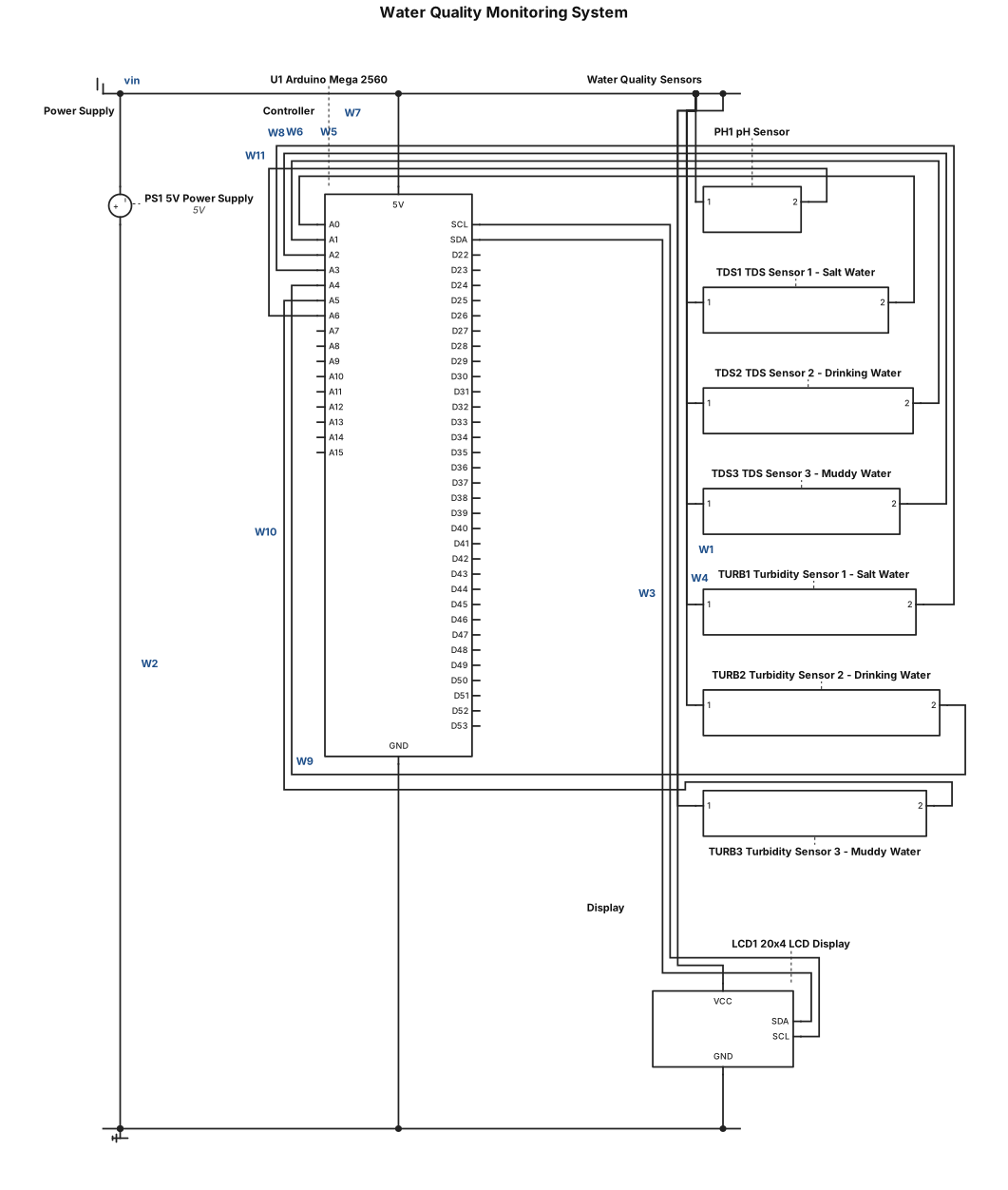
Create a complete wiring diagram for a water quality monitoring system using Arduino Mega 2560, 3 TDS sensors, 3 turbidity sensors, 1 pH sensor, and a 20x4 LCD screen. Connect all sensors and the LCD to the Arduino using a breadboard and jumper wires. The system uses a 5V power supply and has 3 water cups: salt water, drinking water, and muddy water.
ENGINEERING DRAWING ARCHIVE · REAL SPECS
Engineering Diagram Examples from Real Specifications
Browse eligible circuit, ladder, single-line, P&ID, breadboard, timing, and logic drawings with their original prompts.
Browse 540 real creationsCOMMUNITY OUTPUTS · EXACT PROMPTS
Main engineering studio
Showing 121–144 of 380. No stock examples or system defaults. Choose a tool, study a real result, then reopen its prompt as your starting point.
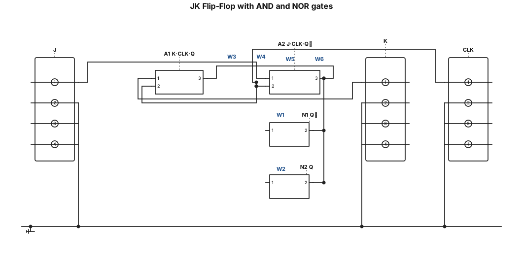
Design a JK Flip-Flop circuit exactly following this architecture: Gate arrangement: 1. Use exactly TWO AND gates in the upper section. 2. Use exactly TWO NOR gates in the lower section. 3. Arrange the two AND gates side by side at the top. 4. Arrange the two NOR gates side by side directly below the AND gates. 5. Connect the output of the left AND gate to one input of the left NOR gate. 6. Connect the output of the right AND gate to one input of the right NOR gate. Inputs and feedback: 7. Provide J, K and CLK inputs. 8. The left AND gate implements K × CLK × Q. 9. The right AND gate implements J × CLK × Q̅. 10. Connect the output Q of the right NOR gate back to the left AND gate. 11. Connect the output Q̅ of the left NOR gate back to the right AND gate. 12. Cross-couple the two NOR gates: - Left NOR output Q̅ connects to an input of the right NOR gate. - Right NOR output Q connects to an input of the left NOR gate. Outputs: 13. Left NOR output: Q̅. 14. Right NOR output: Q. Important design requirements: - Use only AND and NOR gates. - Show all self-feedback connections clearly. - Maintain the exact left-right gate arrangement described above. - Do not use NAND gates, OR gates or additional flip-flop blocks. - Generate a clean, properly labelled gate-level circuit diagram. - The circuit must implement standard JK functionality, including toggle operation when J=K=1.
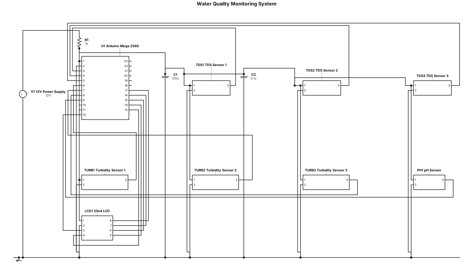
Create a complete wiring diagram for a water quality monitoring system using Arduino Mega 2560, 3 TDS sensors, 3 turbidity sensors, 1 pH sensor, and a 20x4 LCD screen.
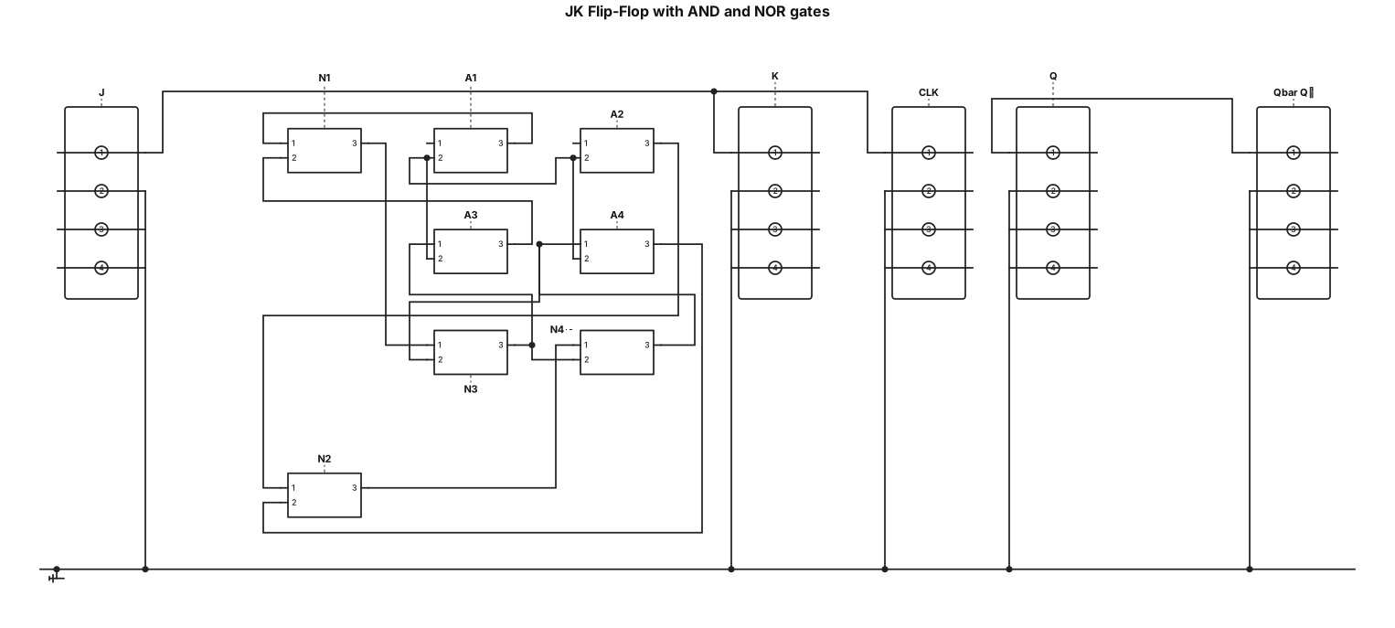
Design a JK Flip-Flop circuit using only AND gates and NOR gates with a self-feedback mechanism. Requirements: 1. Inputs: J, K and CLK (Clock). 2. Outputs: Q and Q̅ (complement of Q). 3. Use AND gates to implement the input logic. 4. Use NOR gates to construct the SR latch. 5. Implement self-feedback by connecting Q feedback to the J input logic and Q̅ feedback to the K input logic. 6. The circuit must follow the JK Flip-Flop truth table: - J=0, K=0: No change. - J=0, K=1: Reset. - J=1, K=0: Set. - J=1, K=1: Toggle. 7. Clearly label all inputs, outputs, gates and feedback connections. 8. Show the complete gate-level circuit diagram with proper wire connections. 9. Ensure that the feedback mechanism is clearly visible. In the form of flipflop ..
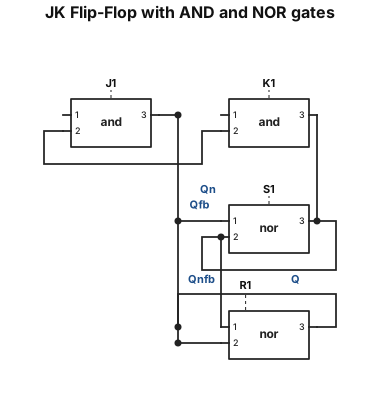
Design a JK Flip-Flop circuit using only AND gates and NOR gates with a self-feedback mechanism. Requirements: 1. Inputs: J, K and CLK (Clock). 2. Outputs: Q and Q̅ (complement of Q). 3. Use AND gates to implement the input logic. 4. Use NOR gates to construct the SR latch. 5. Implement self-feedback by connecting Q feedback to the J input logic and Q̅ feedback to the K input logic. 6. The circuit must follow the JK Flip-Flop truth table: - J=0, K=0: No change. - J=0, K=1: Reset. - J=1, K=0: Set. - J=1, K=1: Toggle. 7. Clearly label all inputs, outputs, gates and feedback connections. 8. Show the complete gate-level circuit diagram with proper wire connections. 9. Ensure that the feedback mechanism is clearly visible. In the for of flipflop ..
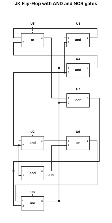
Design a JK Flip-Flop circuit using only AND gates and NOR gates with a self-feedback mechanism. Requirements: 1. Inputs: J, K and CLK (Clock). 2. Outputs: Q and Q̅ (complement of Q). 3. Use AND gates to implement the input logic. 4. Use NOR gates to construct the SR latch. 5. Implement self-feedback by connecting Q feedback to the J input logic and Q̅ feedback to the K input logic. 6. The circuit must follow the JK Flip-Flop truth table: - J=0, K=0: No change. - J=0, K=1: Reset. - J=1, K=0: Set. - J=1, K=1: Toggle. 7. Clearly label all inputs, outputs, gates and feedback connections. 8. Show the complete gate-level circuit diagram with proper wire connections. 9. Ensure that the feedback mechanism is clearly visible.
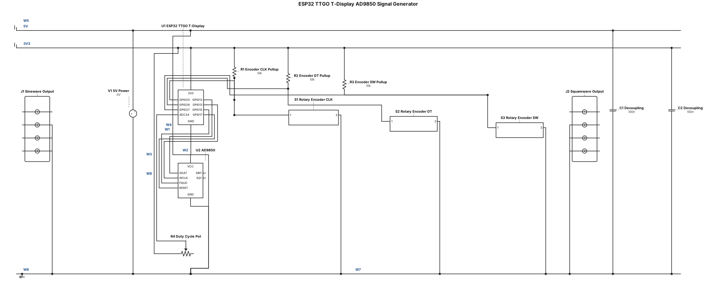
A clear technical wiring diagram and schematic blueprint, vector style, showing a complete electronics project layout with components: ESP32 TTGO T-Display microcontroller, AD9850 module, rotary encoder, potentiometer, signal output jacks, and power supply wires. The layout features clean lines and distinct labels. Connections shown: - ESP32 GPIO 13 connected to AD9850 DATA (SDAT) - ESP32 GPIO 12 connected to AD9850 W_CLK - ESP32 GPIO 15 connected to AD9850 FQ_UD - ESP32 GPIO 17 connected to AD9850 RESET - 5V power rail connected to AD9850 VCC - Common GND connection - Rotary encoder connected to ESP32 GPIO 25 (CLK), 26 (DT), 27 (SW) - Potentiometer connected for squarewave duty cycle control - Output section clearly displaying two separate simultaneous outputs: Sinewave Output from SIN1 pin, and Squarewave Output from SQ1 pin. Professional technical drawing, high contrast, white background, legible text labels, electronic schematic design.
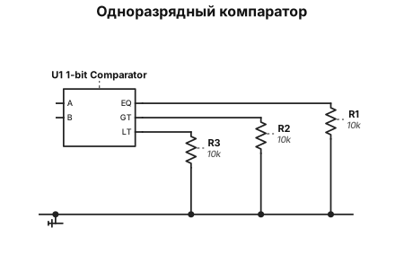
Создай три подробные цифровые логические схемы для лабораторной работы «Исследование цифровых компараторов»: 1. Одноразрядный компаратор с входами A и B и выходами A=B, A>B, A
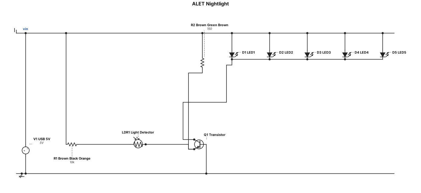
ALET nightlight that uses a USB strive kind of stick. I don’t know what it’s called like like the little attachment. You put uses 5 V. It has a light detector sensor a potential kilometre a transistor, a brown blue red resistor, a brown green brown resistor five of those and five white LEDs the transistor is one of them that looks like a D from the top like eat big cookies and yeah, that should be all you need to make a good you know all that you got
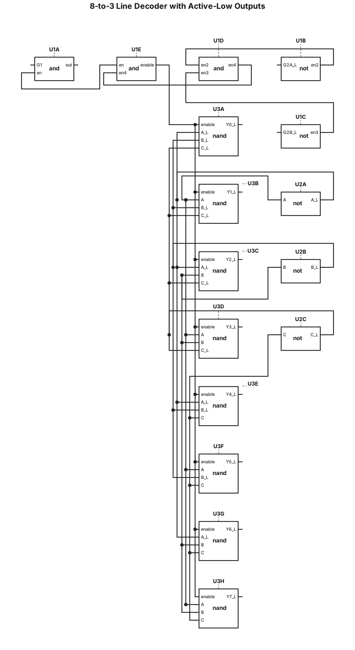
Draw a professional digital logic circuit schematic that accurately reproduces the uploaded reference image. The circuit is an 8-to-3 line decoder / 3-to-8 decoder logic diagram with active-low outputs. Requirements: Use a clean white background. Draw all logic gates using standard digital electronics symbols. On the left side, include the input signals: G1 (pin 6) G2A_L (pin 4) G2B_L (pin 5) A (pin 1) B (pin 2) C (pin 3) Include the input inverter gates and the enable logic gate exactly as shown. Draw the three input signal paths A, B, and C with their inverters and corresponding signal branches. On the right side, draw eight AND-shaped gates with small inversion bubbles at their outputs (NAND gates). Label the outputs from top to bottom: Y0_L (pin 15) Y1_L (pin 14) Y2_L (pin 13) Y3_L (pin 12) Y4_L (pin 11) Y5_L (pin 10) Y6_L (pin 9) Y7_L (pin 7) Reproduce all connecting wires, vertical signal lines, horizontal connections, junction dots, and inverter bubbles. Maintain the exact arrangement and connectivity of the reference image. Use thin black/gray lines, standard electronic symbols, and blue pin numbers. Important: Do not simplify the circuit. Do not omit any wires or connections. Do not add unnecessary components. Ensure every connection and junction matches the reference. Make the final drawing look like a precise engineering schematic, not a 3D illustration. Output: A high-resolution, clean, technically accurate circuit diagram that visually matches the uploaded reference image.
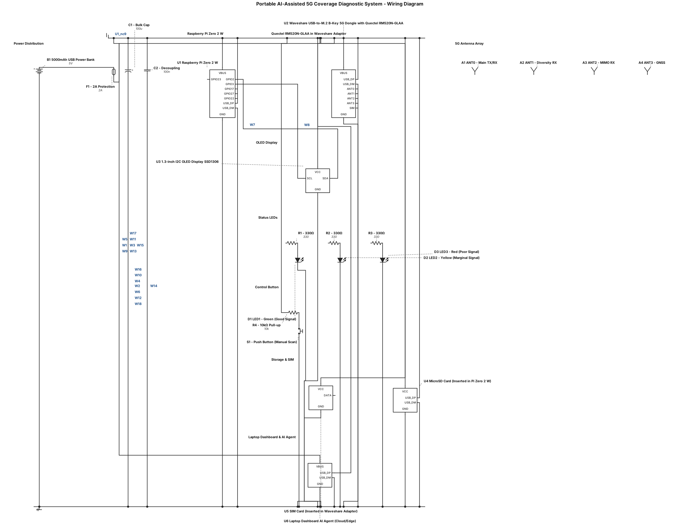
I am an electrical engineering student building a Portable AI-Assisted 5G Coverage Diagnostic System. I need a technically accurate, editable schematic and wiring diagram using these actual components: - Raspberry Pi Zero 2 W - Quectel RM520N-GLAA M.2 5G modem - Waveshare USB-to-M.2 B-Key 5G dongle with four antennas - 1.3-inch I2C OLED display - Three LEDs (green, yellow, red) with appropriate resistors - Push button - 5,000 mAh USB power bank - MicroSD card - SIM card - Laptop dashboard and AI agent The Quectel modem must remain installed inside the Waveshare adapter. Do not redraw it as a separate board or invent different hardware. Create a complete connection diagram showing the correct Raspberry Pi GPIO pin numbers, OLED I2C connections, LED resistors, button wiring, USB data connections, power distribution, and ground connections. Verify USB compatibility and modem power requirements before finalizing the diagram. If additional hardware such as a powered USB hub is required, identify it. Use exact component datasheets where available. Do not invent pinouts or connections. Clearly mark any unverified details. I need both a detailed wiring diagram for physically assembling the prototype and a clean system block diagram for my senior design presentation.
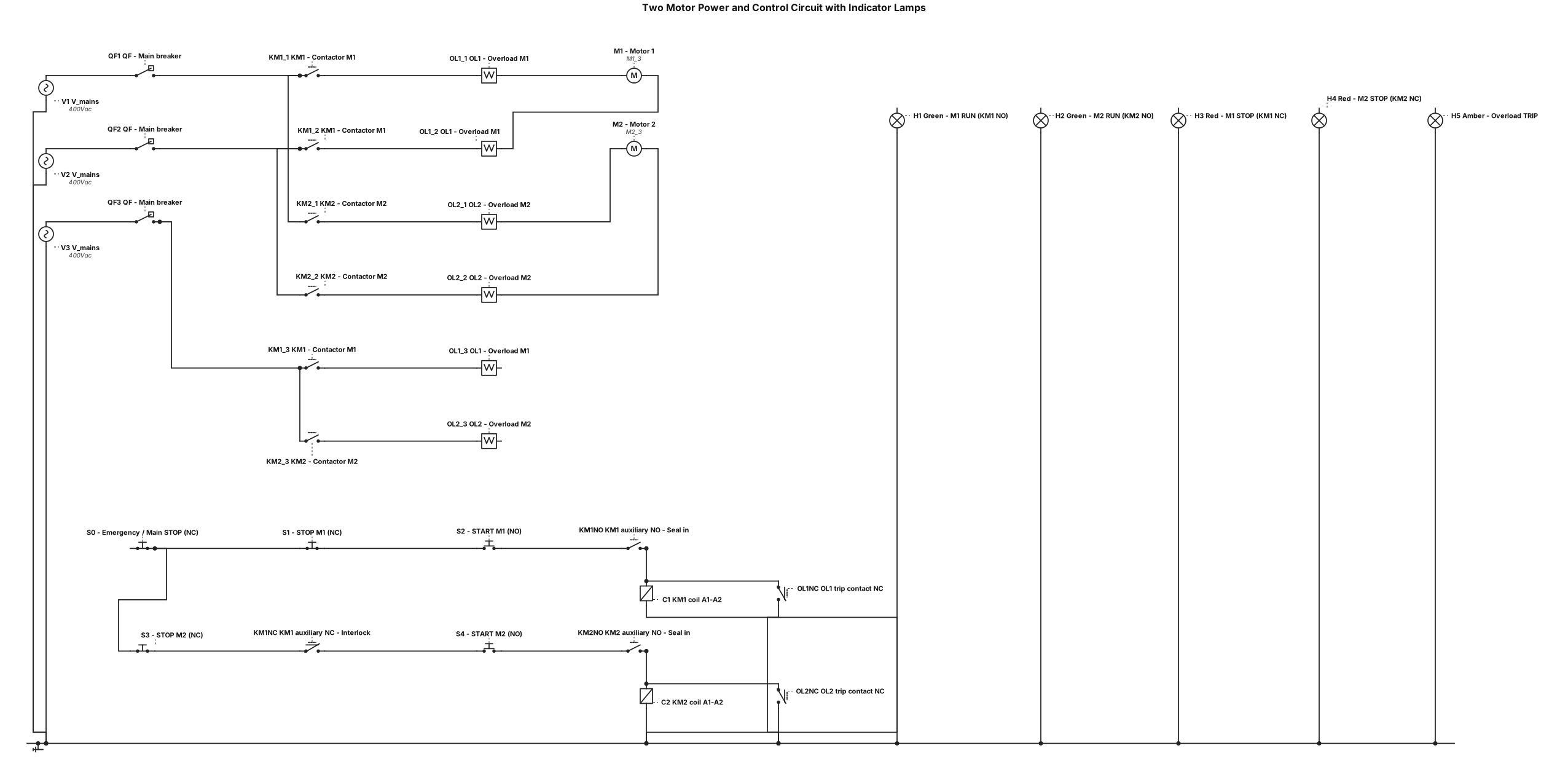
digraph MotorControl { graph [rankdir=TB, splines=ortho, nodesep=0.4, ranksep=0.6, label="TWO MOTOR POWER AND CONTROL CIRCUIT WITH INDICATOR LAMPS", labelloc=t]; node [shape=box, style="rounded", fontname="Arial"]; subgraph cluster_power { label="POWER CIRCUIT - 3 PHASE"; L1; L2; L3; QF [label="QF - Main breaker"]; KM1 [label="KM1 - Contactor M1"]; OL1 [label="OL1 - Overload M1"]; M1 [label="M1 - Motor 1"]; KM2 [label="KM2 - Contactor M2"]; OL2 [label="OL2 - Overload M2"]; M2 [label="M2 - Motor 2"]; L1 -> QF; L2 -> QF; L3 -> QF; QF -> KM1 -> OL1 -> M1; QF -> KM2 -> OL2 -> M2; } subgraph cluster_control { label="CONTROL CIRCUIT - LADDER"; S0 [label="S0 - Emergency / Main STOP (NC)"]; S1 [label="S1 - STOP M1 (NC)"]; S2 [label="S2 - START M1 (NO)"]; KM1NO [label="KM1 auxiliary NO - Seal in"]; C1 [label="KM1 coil A1-A2"]; S3 [label="S3 - STOP M2 (NC)"]; S4 [label="S4 - START M2 (NO)"]; KM1NC [label="KM1 auxiliary NC - Interlock"]; KM2NO [label="KM2 auxiliary NO - Seal in"]; C2 [label="KM2 coil A1-A2"]; OL1NC [label="OL1 trip contact NC"]; OL2NC [label="OL2 trip contact NC"]; S0 -> S1 -> S2 -> C1; S2 -> KM1NO -> C1; S0 -> S3 -> KM1NC -> S4 -> C2; S4 -> KM2NO -> C2; OL1NC -> C1; OL2NC -> C2; } subgraph cluster_lamps { label="INDICATOR LAMPS"; H1 [label="H1 Green - M1 RUN (KM1 NO)"]; H2 [label="H2 Green - M2 RUN (KM2 NO)"]; H3 [label="H3 Red - M1 STOP (KM1 NC)"]; H4 [label="H4 Red - M2 STOP (KM2 NC)"]; H5 [label="H5 Amber - Overload TRIP"]; } }
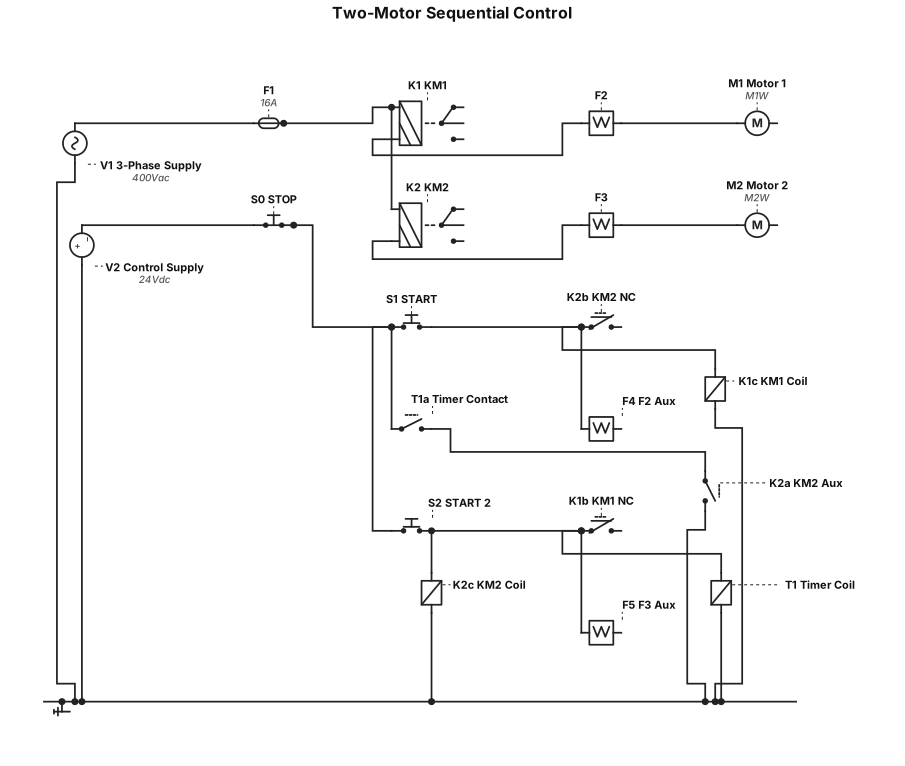
Design the power and control circuits for two three-phase asynchronous motors operating under the following conditions: When the START push button is pressed, only Motor 1 will start. Motor 1 will stop when the STOP push button or the START 2 push button is pressed. When the STOP push button is pressed, Motor 1 will stop and Motor 2 will start. Motor 2 will stop automatically after running for 10 seconds. The system will be protected by thermal overload relays. The two motors must never operate simultaneously. Design the required control and power circuits using standard IEC electrical symbols. Draw the power and control circuits separately, label all components, and show all wiring connections clearly.
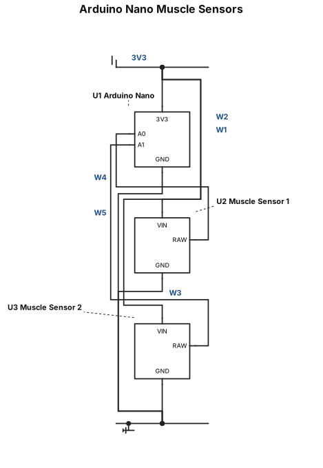
Draw three rectangular circuit blocks labeled Arduino Nano, Muscle Sensor 1, and Muscle Sensor 2. The Arduino Nano block has terminals labeled 3V3, GND, A0, and A1. Each muscle sensor block has terminals labeled VIN, GND, and RAW. Connect 3V3 to both VIN terminals. Connect Arduino GND to both sensor GND terminals. Connect Sensor 1 RAW to A0. Connect Sensor 2 RAW to A1. Show a connection dot at each branching junction.
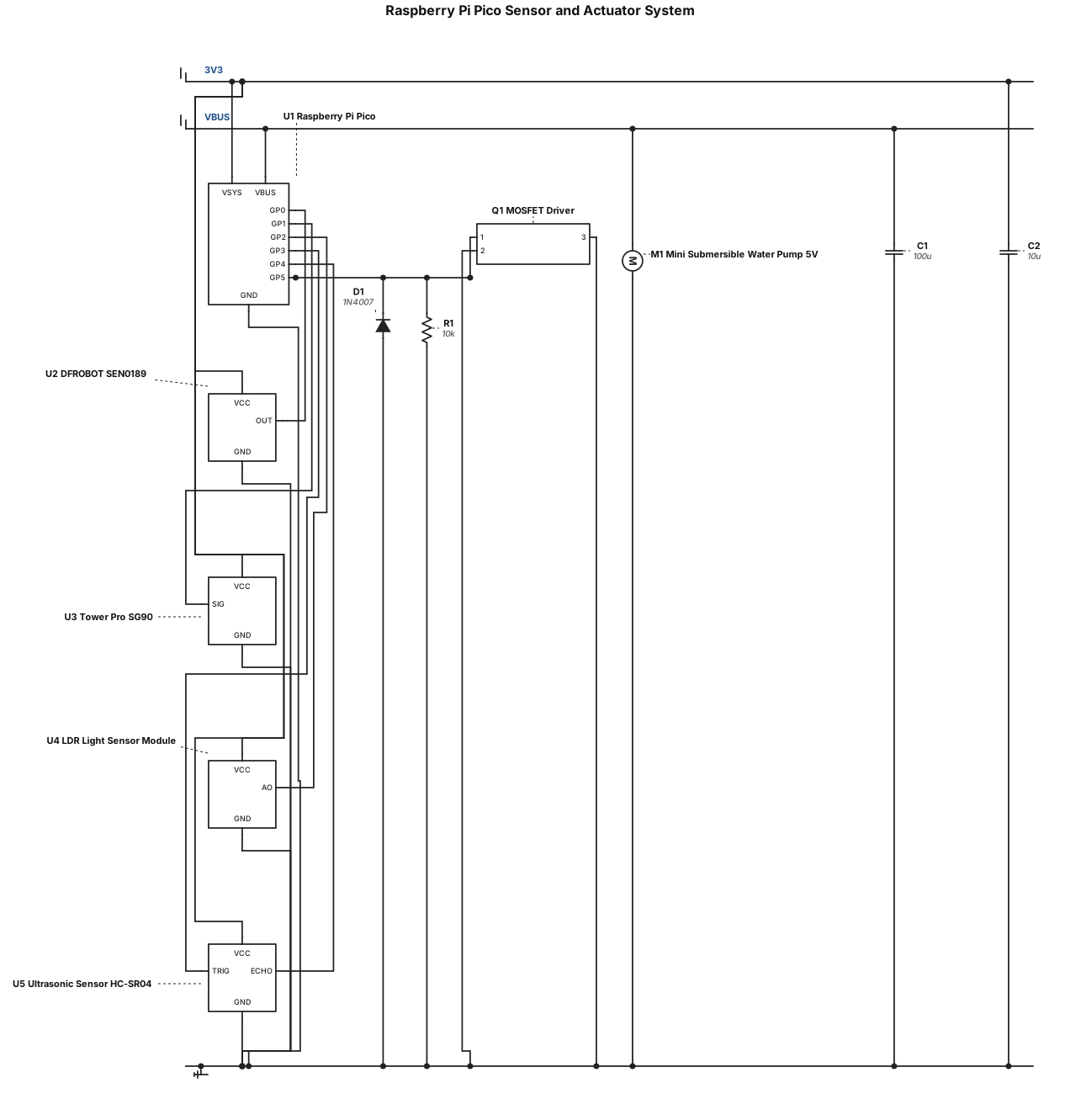
A raspberry Pi Pico connected to a DFROBOT SEN0189, Tower Pro SG90, LDR Light Sensor Module, Ultrasonic Sensor, and Mini Submersible Water Pump (5 Volts). Use a breadboard for any extra connections.
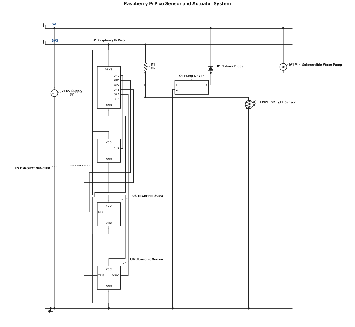
A raspberry Pi Pico connected to a DFROBOT SEN0189, Tower Pro SG90, LDR Light Sensor Module, Ultrasonic Sensor, and Mini Submersible Water Pump (5 Volts)
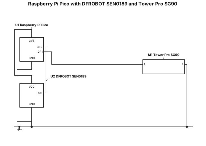
A raspberry Pi Pico connected to a DFROBOT SEN0189 and Tower Pro SG90
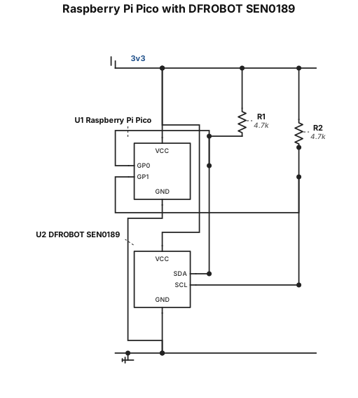
A raspberry Pi Pico connected to a DFROBOT SEN0189
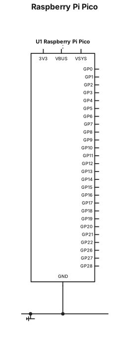
A raspberry Pi Pico
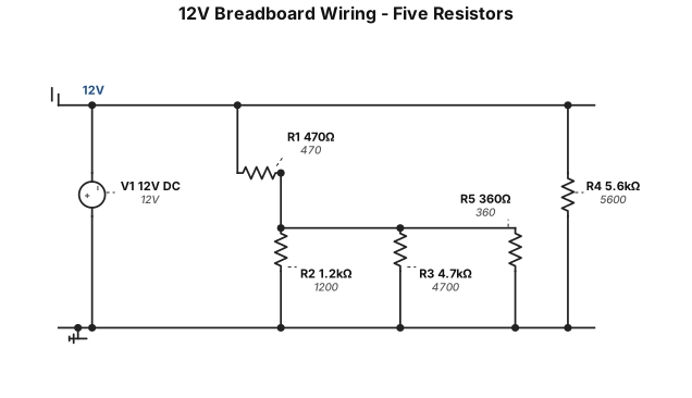
Create a breadboard wiring diagram for a 12V DC circuit using five resistors. R1 = 470 ohms, R2 = 1200 ohms, R3 = 4700 ohms, R4 = 5600 ohms, R5 = 360 ohms. Connect R4 directly between 12V positive and ground. Connect R1 from 12V positive to junction B. Connect R2, R3, and R5 in parallel between junction B and ground. Show a realistic solderless breadboard with exact numbered holes, correct resistor colour bands, and coloured jumper wires. Label every resistor and connection. Do not generate only a schematic.

Нарисуй полноценную электрическую принципиальную схему по следующим условиям. Используй стандартные электрические символы IEC и оформи чертёж как настоящую промышленную электрическую схему, а не блок-схему. 1. Ввод питания * Вводной кабель: 5×10 мм². * Главный выключатель: S1. * Автоматический выключатель: F1, 3-полюсный, B10 A. * Блок питания T1: 24 V DC. 2. Двигатель M1 * Двигатель M1 мощностью 2,2 kW. * Защитный аппарат Q1. * Контакторы K1 и K2. * Трёхпозиционный переключатель. * Кабель переключателя: 4×1,0 мм². 3. Двигатель M2 * Защитный аппарат Q2. * Частотный преобразователь A1. * Двигатель M2 мощностью 11 kW. * Трёхпозиционный переключатель и потенциометр. * Кабель двигателя: 4×4 мм². 4. Цепь безопасности * Реле безопасности с четырьмя кнопками аварийного останова E-STOP. * Два канала безопасности CH1 и CH2 проходят через кнопки E-STOP. * Реле R1 отключает три линии питания 24 V DC. Требования к результату: * Покажи все элементы и реальные электрические соединения между ними. * Отдельно отобрази силовые цепи, цепи управления и цепь безопасности. * Подпиши элементы, контакты, проводники, кабели и напряжения. * Используй стандартные условные обозначения контакторов, двигателей, автоматов, реле, переключателей и частотного преобразователя. * Сделай аккуратный технический чертёж, похожий на схемы из учебника по промышленной электротехнике. * Результат предоставь в формате PDF или SVG с высоким качеством и возможностью увеличения. Важно: не создавай блок-схему и не заменяй электрические соединения стрелками. Не придумывай отсутствующие данные. Если для правильной схемы не хватает информации, укажи, что именно нужно уточнить. Проверь правильность соединений и обозначений. Не утверждай, что схема полностью корректна, если это не проверено.
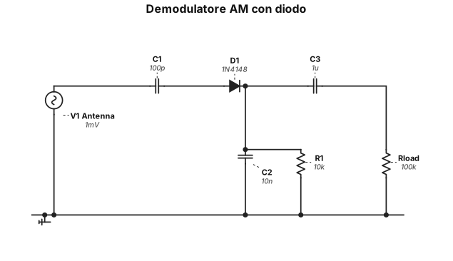
demudulatore am con diodo
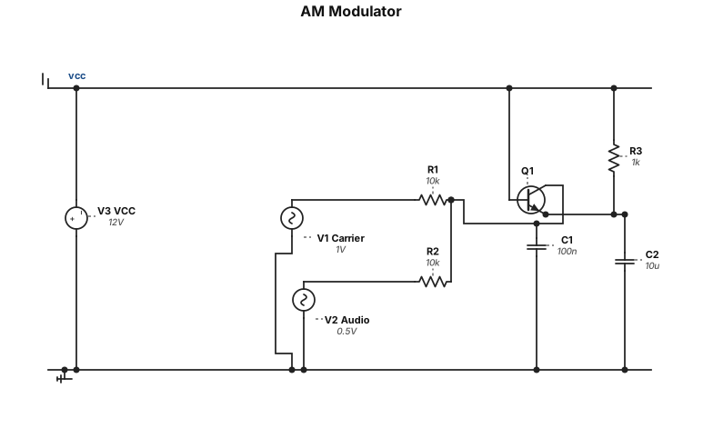
am modulator
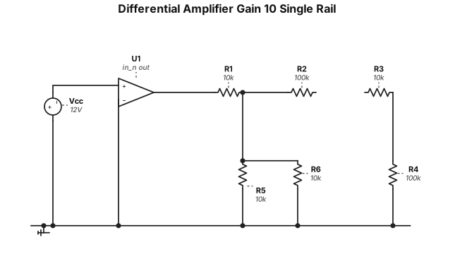
Differential amplifier gain 10 with A.O. single rail show operational amplifier power supply