
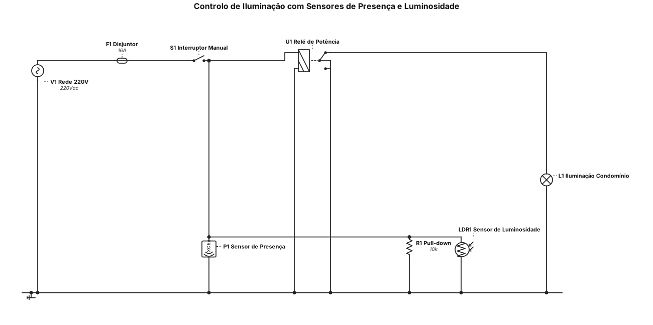
Controlo de iluminação com uso de sensores de presença e luminosidade para um condomínio residencial
ENGINEERING DRAWING ARCHIVE · REAL SPECS
Engineering Diagram Examples from Real Specifications
Browse eligible circuit, ladder, single-line, P&ID, breadboard, timing, and logic drawings with their original prompts.
Browse 543 real creationsCOMMUNITY OUTPUTS · EXACT PROMPTS
Main engineering studio
Showing 169–192 of 380. No stock examples or system defaults. Choose a tool, study a real result, then reopen its prompt as your starting point.
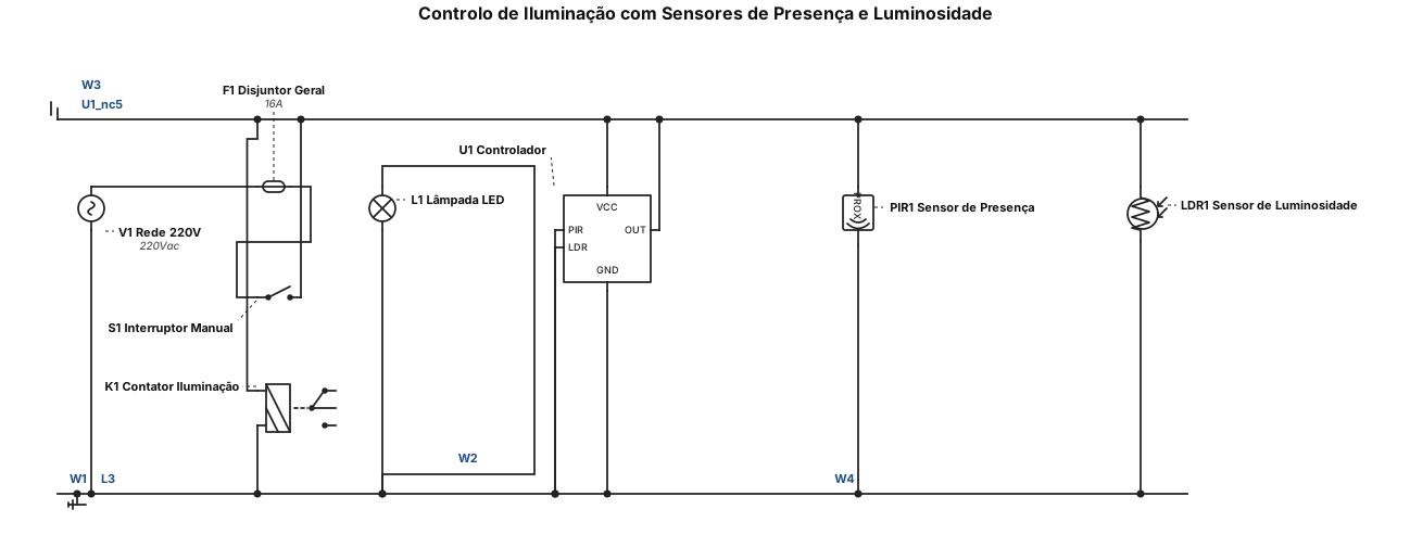
Controlo de iluminação com uso de sensoress de presença e luminosidade para um condomínio residencial
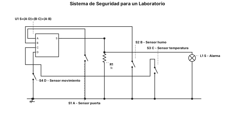
Sí. En las imágenes que me enviaste, la actividad dice esto: Sistema de Seguridad para un Laboratorio Entradas: - A — Sensor puerta - 1 = Puerta abierta - 0 = Puerta cerrada - B — Sensor humo - 1 = Detecta humo - 0 = No detecta humo - C — Sensor temperatura - 1 = Temperatura elevada - 0 = Temperatura normal - D — Sensor de movimiento - 1 = Detecta movimiento - 0 = No detecta movimiento Salida: - S — Alarma - 1 = Activa - 0 = Inactiva Cuándo encender la alarma La pizarra indica que la alarma debe encenderse cuando: I) Puerta abierta y detecta movimiento. II) Presencia de humo y temperatura elevada. III) Puerta abierta y presencia de humo, independientemente de los otros sensores. En cualquier otro caso, la alarma debe permanecer apagada. Y finalmente pide: i) Determinar la función lógica para la salida y validarla en una calculadora de mapas. ii) Implementarla y simularla en Tinkercad. Por eso, la función que corresponde es: \[ \boxed{S=(A\cdot D)+(B\cdot C)+(A\cdot B)} \] La primera imagen muestra además que después deben pasar esa tabla de verdad a un mapa de Karnaugh.
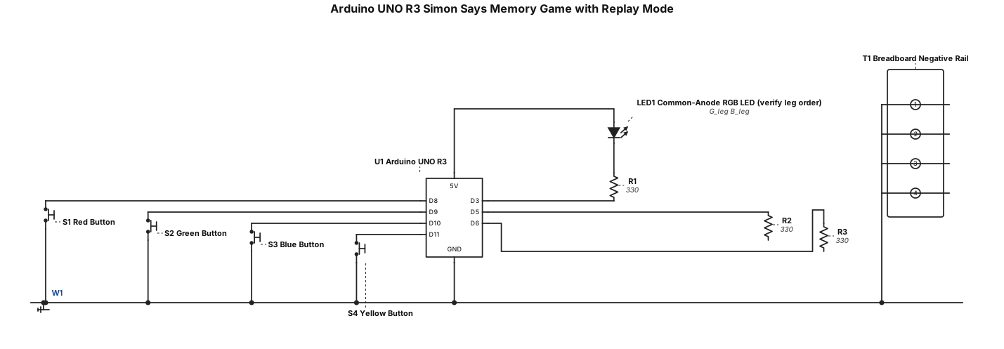
Create a clear, accurate breadboard wiring diagram for an Arduino UNO R3 Simon Says memory game with replay mode. Use one common-anode 4-pin RGB LED, four push buttons, three 330-ohm resistors, a breadboard, and jumper wires. Connect the LED's common-anode leg to 5V. Connect its red, green, and blue colour legs through separate 330-ohm resistors to Arduino pins D3, D5, and D6, respectively. Connect the red, green, blue, and yellow buttons to D8, D9, D10, and D11, respectively. Connect the opposite terminal of each button to GND. Use INPUT_PULLUP, so no extra button resistors are required. Connect Arduino GND to the breadboard's negative rail. Label all pins, components, and connections. Use a neat top-down view, with every wire ending at the correct pin or breadboard row. Do not invent the RGB LED's physical leg order; label each leg by function and show that the exact leg positions must be verified.
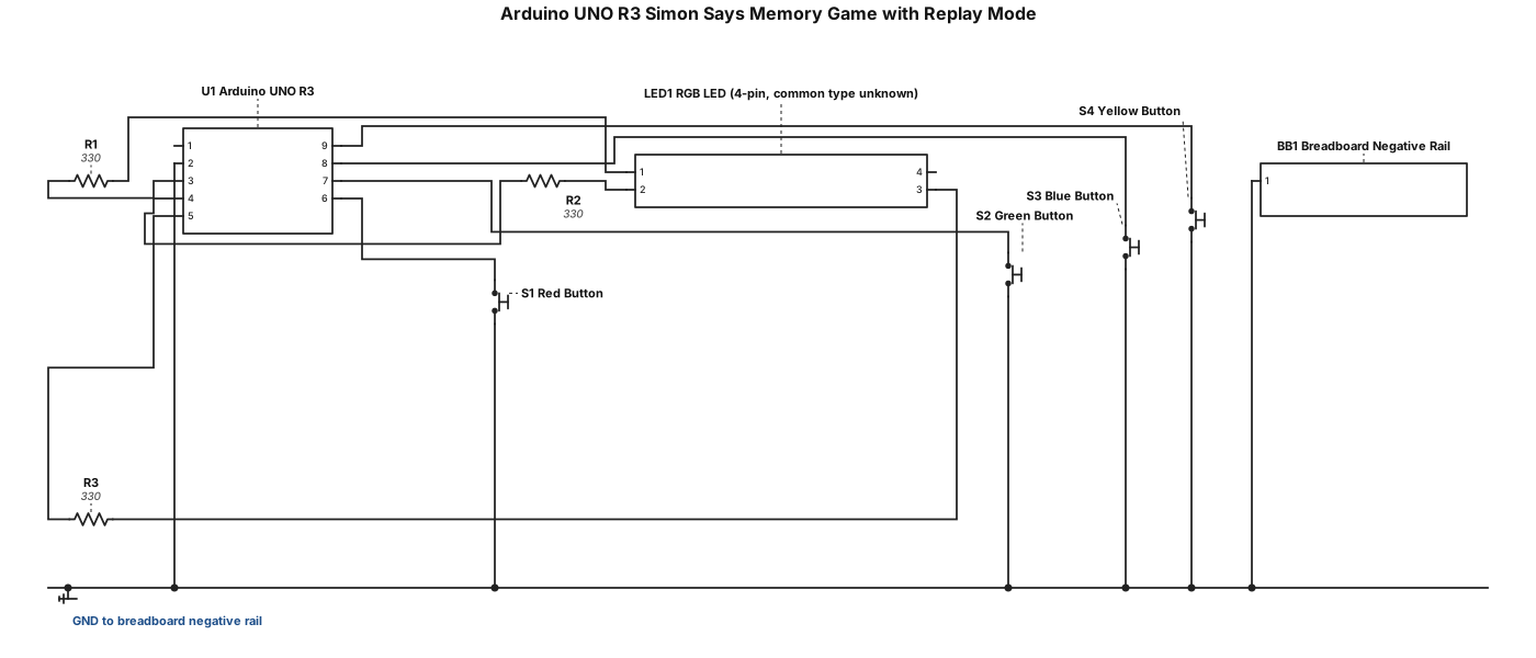
Create a clear, accurate wiring diagram for an Arduino UNO R3 Simon Says memory game with replay mode. Show one 4-pin RGB LED, four push buttons, three 330-ohm resistors, a breadboard, and jumper wires. Connect the LED red, green, and blue channels through separate resistors to pins D3, D5, and D6. Connect the red, green, blue, and yellow buttons to D8, D9, D10, and D11, respectively. Connect the other side of every button to GND. Use INPUT_PULLUP, so no button resistors are needed. Connect Arduino GND to the breadboard's negative rail. Label every pin and wire clearly. Do not guess the RGB LED's leg order or common-pin type; mark them as unknown until verified. Use a clean top-down view and ensure every wire connects to the correct point.

b) Design and implement a 4 bit Logic unit using a MUX. AND, OR, XOR, NOT ehre is the gates
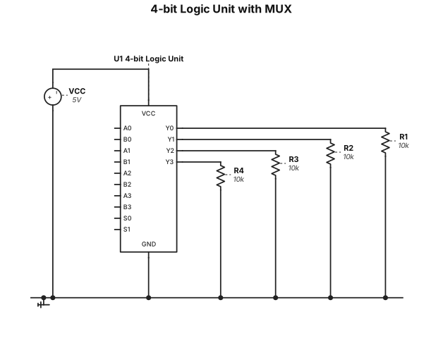
b) Design and implement a 4 bit Logic unit using a MUX. AND, OR, XOR, NOT
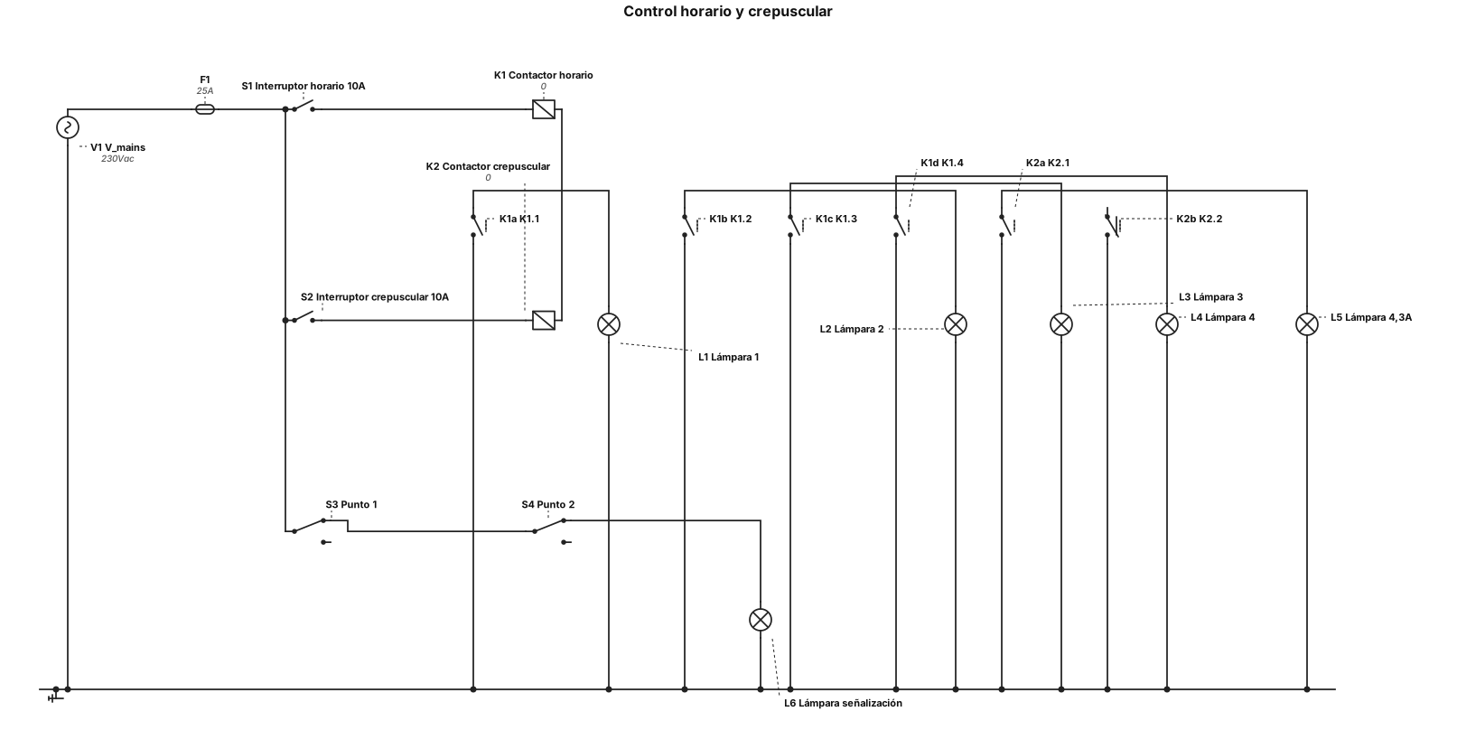
En una instalación eléctrica un interruptor horario de 10 A debe accionar 4 lámparas con un consumo total de 18 A, y por otra parte, un interruptor crepuscular de 10 A debe accionar una lámpara de 4,3 A cuando no haya luz solar, y una lámpara de señalización cuando haya luz solar. Esta última también se puede encender a través desde 2 puntos con mecanismos manuales.
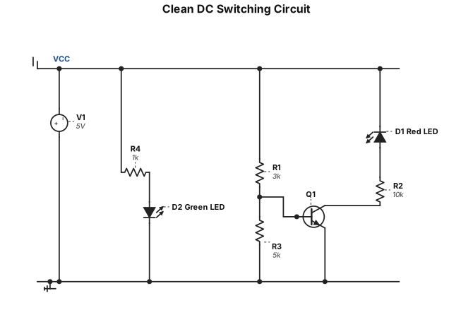
Clean DC switching circuit: A 5V DC power source (V1) with its positive terminal connected to a common VCC rail and negative to ground (GND). A 3 kΩ resistor (R1) connected in series from VCC to the base of an NPN transistor (Q1). The collector of Q1 is connected through a 10 kΩ resistor (R2) and a red LED (D1) in series back to VCC. A 5 kΩ resistor (R3) connected from the base of Q1 to ground. The emitter of Q1 is connected directly to ground. A green LED (D2) connected in series with its protection resistor from VCC to ground. the circuit has a cos φ of 1.5
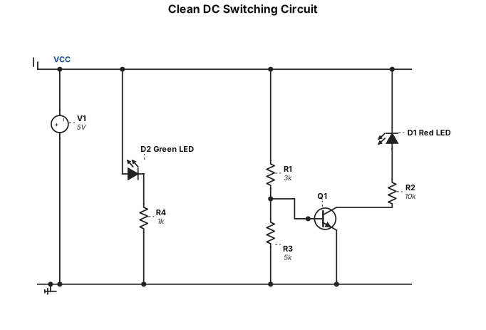
Clean DC switching circuit: A 5V DC power source (V1) with its positive terminal connected to a common VCC rail and negative to ground (GND). A 3 kΩ resistor (R1) connected in series from VCC to the base of an NPN transistor (Q1). The collector of Q1 is connected through a 10 kΩ resistor (R2) and a red LED (D1) in series back to VCC. A 5 kΩ resistor (R3) connected from the base of Q1 to ground. The emitter of Q1 is connected directly to ground. A green LED (D2) connected in series with its protection resistor from VCC to ground.
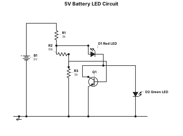
A circuit powered by a 5V battery, featuring a 3-kiloohm resistor, a 10-kiloohm resistor, a 5-kiloohm resistor, an NPN transistor, a red LED, and a green LED; the circuit has a cos φ of 1.5.
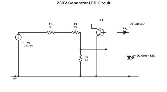
A circuit powered by a 230V generator, comprising a 3 kΩ resistor, a 10 kΩ resistor, a 5 kΩ resistor, an NPN transistor, a red LED, and a green LED; the circuit has a cos φ of 1.5.
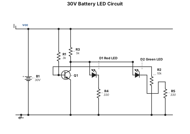
A circuit powered by a 30V battery, featuring a 3 kΩ resistor, a 10 kΩ resistor, a 5 kΩ resistor, an NPN transistor, a red LED, and a green LED; the circuit has a cos φ of 1.5.
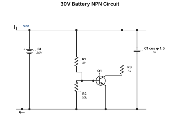
A circuit powered by a 30V battery, featuring a 3-kiloohm resistor, a 10-kiloohm resistor, a 5-kiloohm resistor, and an NPN transistor; the circuit has a cos φ of 1.5.
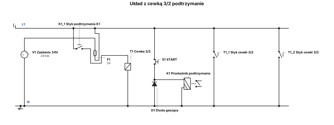
Zbuduj mi układ elektryczny z cewką 3/2 przekaźnikiem który musi być podtrzymany . Z czasówką i przyciskiem Który na starcie aktywuje cały program
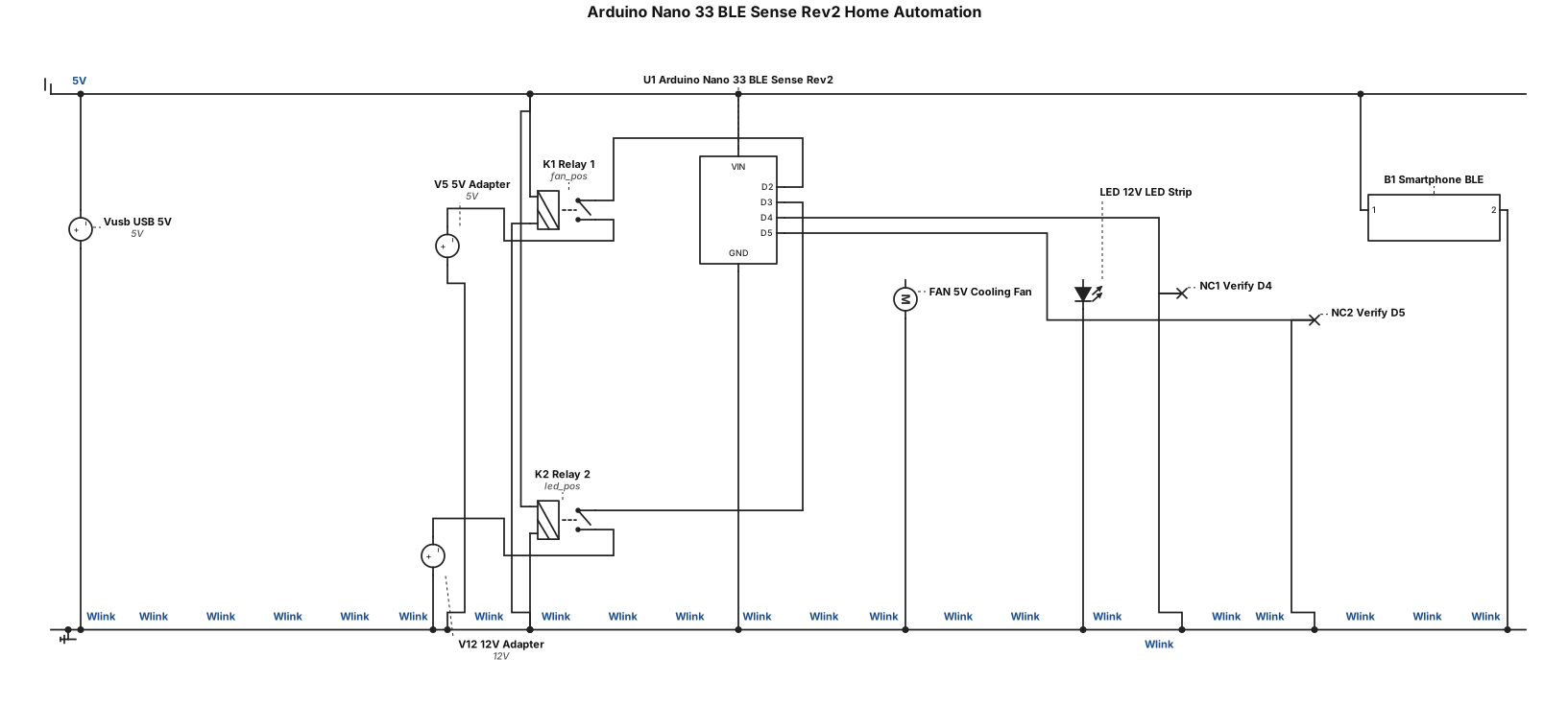
Draw an actual electronic wiring diagram for an Arduino Nano 33 BLE Sense Rev2 home automation project. Connect Arduino GPIO pins to a 4-channel 5V relay module. Use relay channel 1 to switch a 5V cooling fan powered by a 5V adapter, and relay channel 2 to switch a 12V LED strip powered by a separate 12V adapter. Show the USB cable powering the Arduino and a smartphone communicating wirelessly over BLE. Draw real wires between component pins and relay terminals, and label GPIO, IN1, IN2, VCC, GND, COM, NO, positive and negative terminals. Keep the 5V and 12V circuits separate. Do not invent unknown pin connections; mark them for verification. Show a practical electrical schematic, not a block diagram.
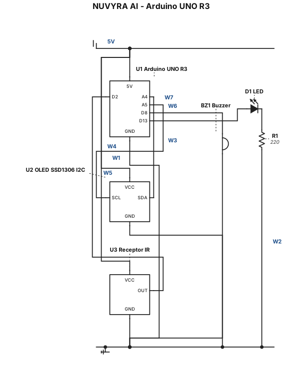
Genera un esquema eléctrico claro y de alta resolución para mi proyecto NUVYRA AI con Arduino UNO R3, pantalla OLED SSD1306 I2C, receptor infrarrojo para control remoto, buzzer y LED con resistencia de 220 ohmios. Etiqueta cada pin y cada cable. OLED: SDA a A4 y SCL a A5. Receptor infrarrojo: señal a D2. Buzzer positivo a D8 y negativo a GND. LED controlado por D13 con resistencia de 220 ohmios. Indica las conexiones de alimentación según las especificaciones de cada componente. No inventes conexiones. Organiza los cables por colores y evita que se crucen.
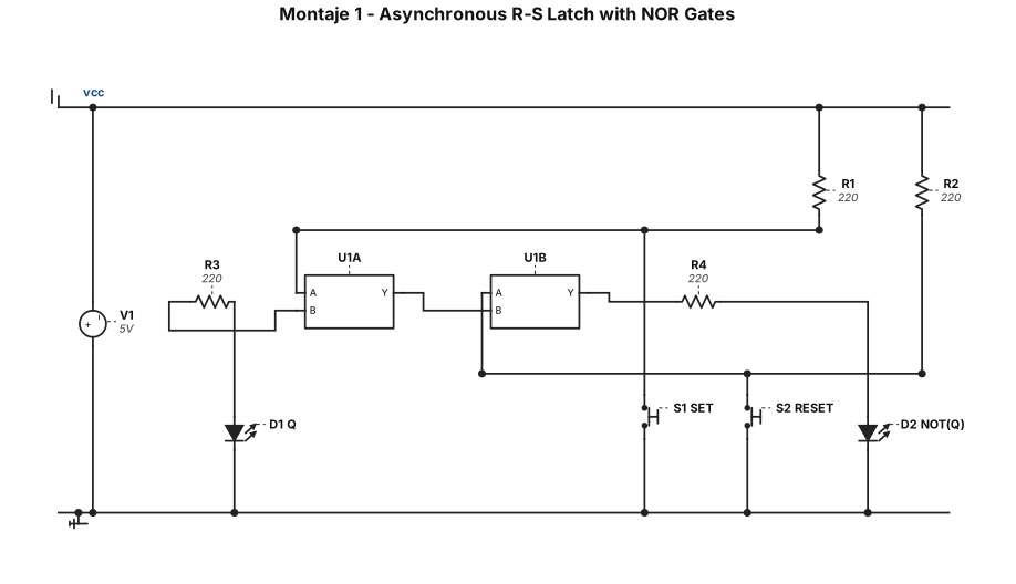
Create an electronic circuit that reproduces Montaje 1 of my Digital Electronics laboratory practice. The circuit is an asynchronous R-S latch using two cross-coupled NOR gates (74LS02). IMPORTANT: Follow the exact component arrangement and electrical connections below. Do not redesign, optimize, simplify, or replace any components. COMPONENTS: - 1 DC power supply: 5 V - 2 NOR gates: U1A and U1B (74LS02) - 2 normally open switches: SET and RESET - 4 resistors: R1, R2, R3, R4, all 220 ohms - 2 LEDs: D1 labeled Q and D2 labeled NOT(Q) - Ground connections INPUT CONNECTIONS: 1. Connect one terminal of the SET switch to GND. 2. Connect the other terminal of SET to the upper input of NOR gate U1A. 3. Connect R1 (220 ohms) between +5 V and the SET input node. 4. Connect one terminal of the RESET switch to GND. 5. Connect the other terminal of RESET to the lower input of NOR gate U1B. 6. Connect R2 (220 ohms) between +5 V and the RESET input node. NOR GATE CONNECTIONS: 7\. Connect the output of U1A to one input of U1B. 8\. Connect the output of U1B to the remaining input of U1A. 9\. Keep both NOR gates cross-coupled to form the R-S latch. OUTPUT CONNECTIONS: 10\. Connect the output of U1A through R3 (220 ohms) to the anode of LED D1 (Q). 11\. Connect the cathode of D1 to GND. 12\. Connect the output of U1B through R4 (220 ohms) to the anode of LED D2 (NOT Q). 13\. Connect the cathode of D2 to GND. LAYOUT: - SET switch at the upper left. - RESET switch at the lower left. - R1 and R2 vertically connected to +5 V. - U1A above U1B in the center. - D1 (Q) to the right of U1A. - D2 (NOT Q) to the right of U1B. - Show the feedback wires clearly between the two NOR gates. - Label all components and values. The final circuit must visually match the reference laboratory schematic as closely as possible. Do not add extra gates, capacitors, clocks, or other components. Make the switches interactive.
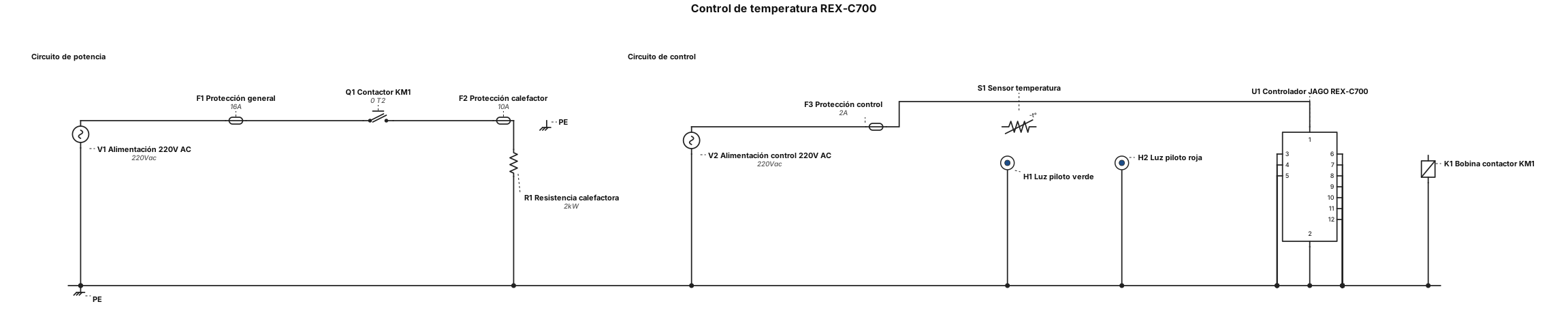
Quiero diseñar un circuito eléctrico de control de temperatura para un proyecto de electromecánica. Necesito que me ayudes a crear el diagrama eléctrico completo, con símbolos normalizados y conexiones claramente identificadas. COMPONENTES 1. Controlador digital de temperatura JAGO REX-C700. 2. Alimentación de 220 V AC. 3. Contactor electromagnético con bobina de 220 V AC. 4. Resistencia calefactora. 5. Sensor de temperatura compatible con el controlador, cuyo tipo está pendiente de confirmar. 6. Una luz piloto verde. 7. Una luz piloto roja. 8. Protecciones eléctricas adecuadas. CIRCUITO DE CONTROL Representa la alimentación del controlador, la conexión del sensor, la salida de control y la bobina del contactor. Verifica los terminales exactos del REX-C700 antes de asignar conexiones. Incluye las dos luces piloto: - Luz verde: debe indicar que la resistencia calefactora está funcionando; preferiblemente, que el contactor está activado. - Luz roja: debe indicar que se alcanzó la temperatura configurada y que la calefacción está detenida. Si estas funciones requieren contactos auxiliares o una configuración específica del controlador, indícalo en el esquema. CIRCUITO DE POTENCIA Representa la alimentación de 220 V AC, las protecciones eléctricas, los contactos principales del contactor y la resistencia calefactora, incluyendo la puesta a tierra correspondiente. PRESENTACIÓN - Separa el circuito de control del circuito de potencia. - Utiliza símbolos eléctricos normalizados. - Identifica los bornes, componentes y conexiones. - Explica el funcionamiento paso a paso. - No inventes terminales ni conexiones del controlador. - Si falta información, pregúntame antes de finalizar el esquema. - Si es posible, genera un diagrama editable y simulable. Quiero un circuito profesional, ordenado y fácil de entender para un estudiante de electromecánica.
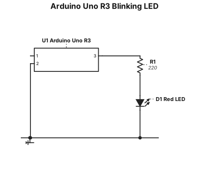
Create a complete and clearly labelled Arduino Uno R3 circuit diagram for a blinking LED experiment, suitable for a beginner's practical exam. Components: Arduino Uno R3, one red LED, one 220-ohm resistor, and jumper wires. Connections: 1. Connect Arduino digital pin 7 to one end of the 220-ohm resistor. 2. Connect the other end of the resistor to the LED's long leg (anode, positive). 3. Connect the LED's short leg (cathode, negative) to Arduino GND. 4. Do not connect the LED directly to 5V; control it using digital pin 7. Expected result: The LED should turn ON for one second and OFF for one second repeatedly. Also provide a visual breadboard-style wiring diagram, labels for every Arduino pin and component, complete Arduino C++ code, simple step-by-step wiring instructions, and a short explanation of how the circuit works.
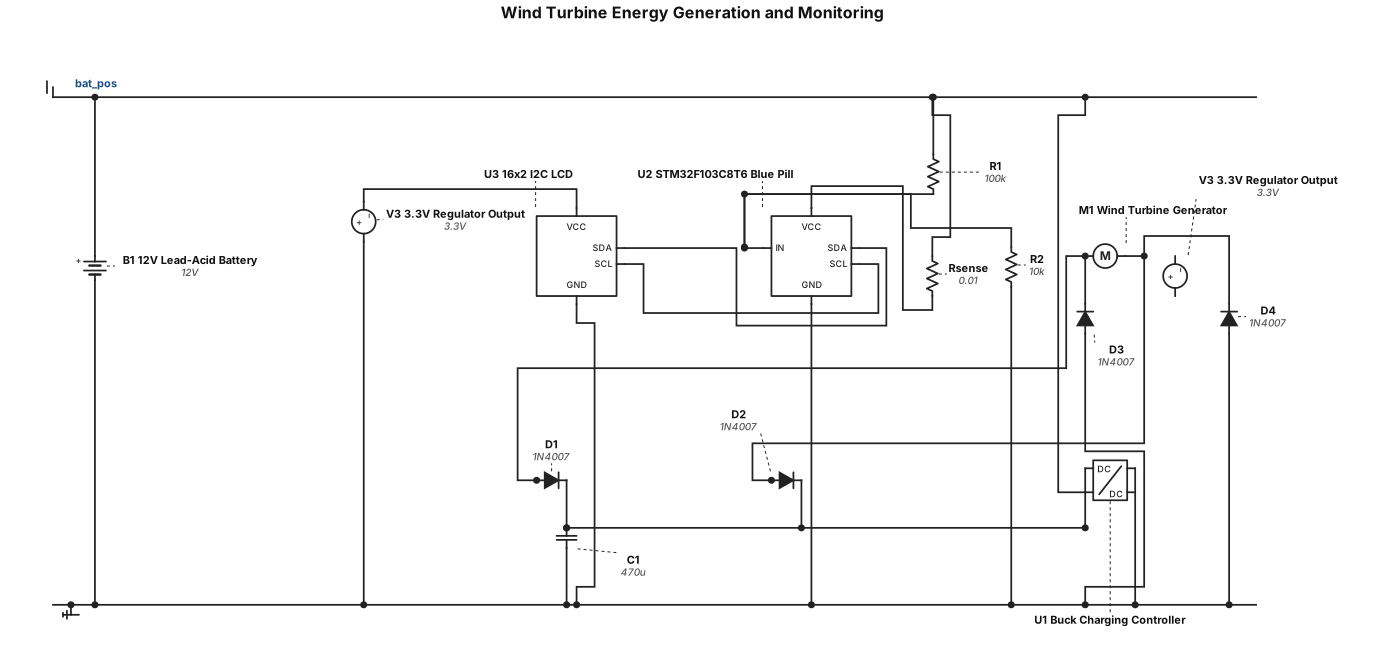
Build a wind turbine energy generation and monitoring project. The system should include: 1. A DC motor used as a wind turbine generator. 2. A bridge rectifier, if required by the generator output. 3. A smoothing capacitor. 4. A DC-DC buck charging controller. 5. A 12V lead-acid battery. 6. A voltage sensor and current sensor. 7. An STM32F103C8T6 Blue Pill microcontroller. 8. A 16x2 I2C LCD display. The STM32 should monitor generator voltage, charging current, output power, and battery voltage, then display the readings on the LCD. Generate the complete circuit schematic with labelled components, pin connections, power rails, and common ground. Use components supported by your simulator and identify any components that cannot be simulated.
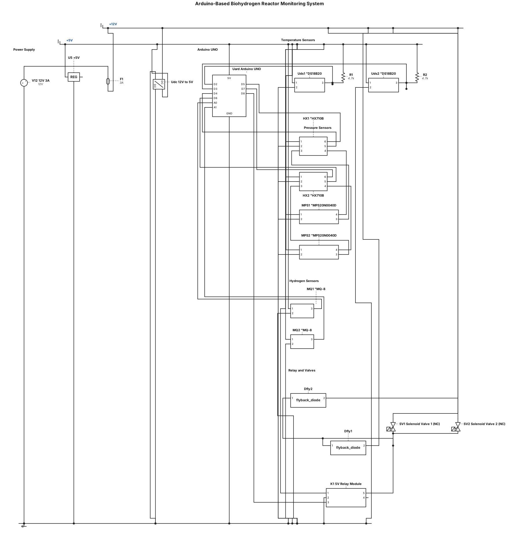
Create a simple conventional electrical schematic on a white background. Use standard electronic symbols, straight horizontal and vertical wires, and clear labels. Do not create an infographic or a realistic drawing. Arrange the circuit in three sections: **LEFT: Power supply** - Place a 12 V, 3 A DC power supply at the bottom left. - Add a 3 A fuse in series with the positive supply. - Place a 12 V to 5 V DC-DC converter next to the supply. - Label the outputs +12 V, +5 V, and GND. **CENTER: Arduino and temperature sensors** - Place an Arduino UNO in the center. - Above it, place two DS18B20 temperature sensors, one above the other. - Connect sensor 1 data to D2 and sensor 2 data to D3. - Add one 4.7 kΩ pull-up resistor from each data line to +5 V. **CENTER-LEFT: Pressure sensors** - Place two MPS20N0040D pressure sensors, one above the other. - Place one HX710B module beside each pressure sensor. - Connect module 1 DT to D4 and SCK to D5. - Connect module 2 DT to D6 and SCK to D7. - Show power and ground connections. Label uncertain sensor terminals "VERIFY PINOUT". **RIGHT: Hydrogen sensors** - Place two MQ-8 modules, one above the other. - Connect the first analog output AO to Arduino A0. - Connect the second analog output AO to Arduino A1. - Connect both modules to +5 V and GND. **BOTTOM-RIGHT: Relay and valves** - Place a 5 V single-channel relay module. - Connect relay IN to Arduino D8. - Place two 12 V, 1 A normally closed solenoid valves to the right of the relay. - Connect both valves in parallel through the relay contacts COM and NO. - Add one flyback diode across each valve, with cathode toward +12 V. Use a common ground reference and label all connections. Keep the drawing simple, organized, and readable. Include the title "Arduino-Based Biohydrogen Reactor Monitoring System". Do not add decorative elements. Do not invent unknown connections. Prioritize a clear electrical schematic over visual detail.
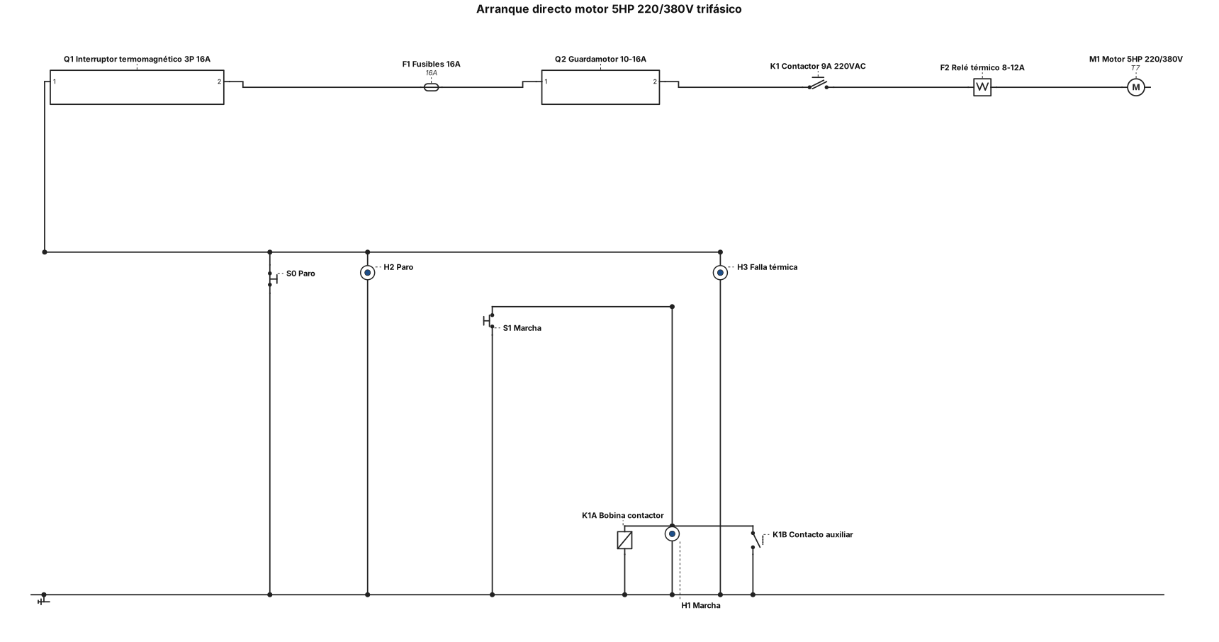
) Grafique un circuito de mando, potencia, y los diagramas Ladder y Bloque para la programación del PLC de los siguientes automatismos, identificando todos los elementos necesarios para realizarlo. Explique detalladamente la lógica de funcionamiento del automatismo mencionando la acción de cada elemento. Realice la simulación en Cadesimu, PC simu o Logo Soft Confort según corresponda a cada clase, y la ejecución en un tablero real. Identificar las características electricas de todos los elementos que intervienen para su selección. Los automatismos son: Arranque directo de un motor asíncrono o de inducción de 5HP 220/380V trifásico. El sistema debe tener testigos lumínicos y protecciones (Guardamotor, Termomagnética, fusibles, relee térmico, etc) acorde a la potencia del motor
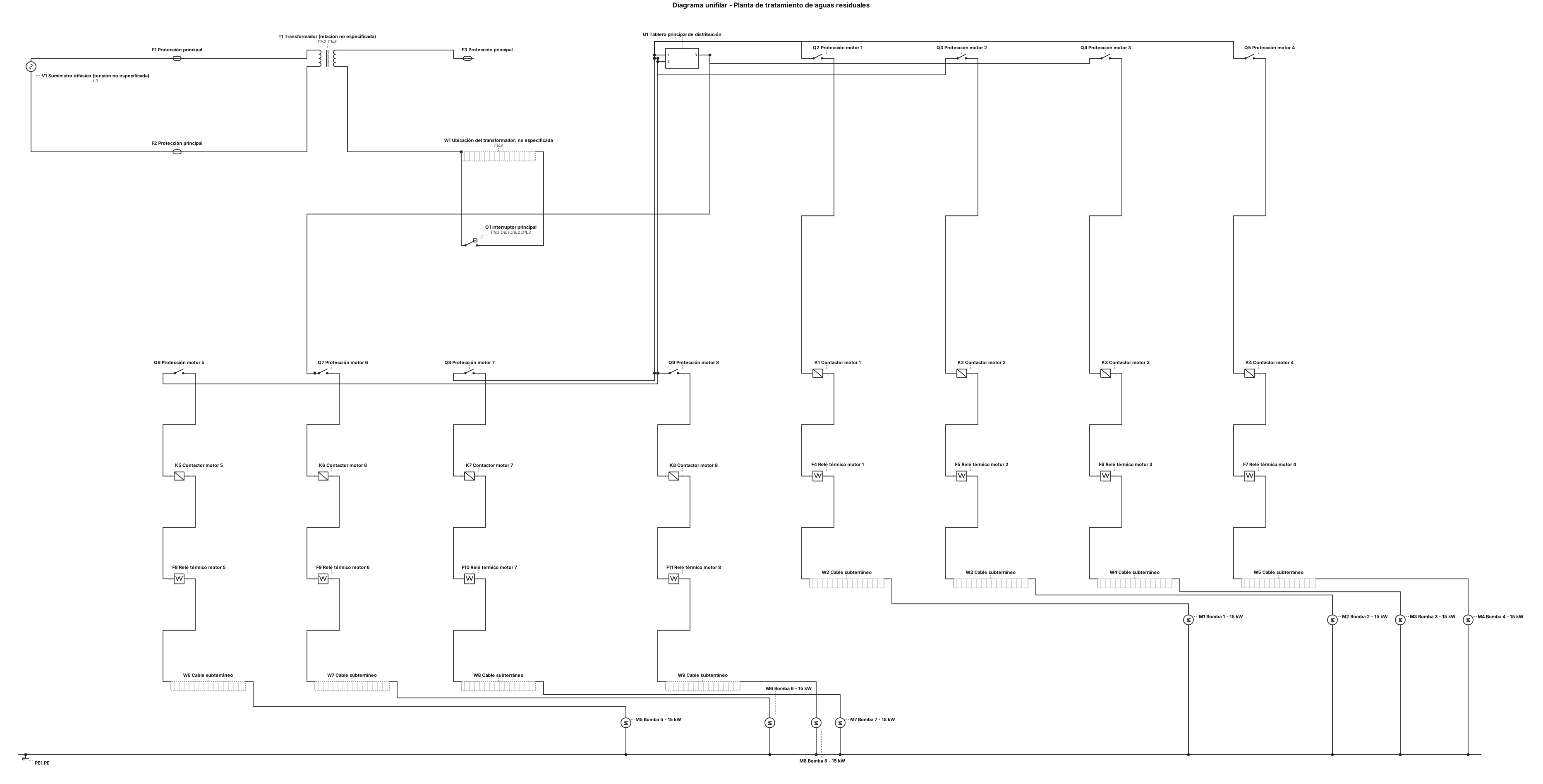
Create a technical single-line electrical diagram for an industrial wastewater treatment plant with eight submersible three-phase pumps, each rated at 15 kW. Include: Three-phase electrical supply. Main protection. Main distribution panel. Eight separate outgoing motor circuits. Individual protection for each pump motor. Motor control equipment for each pump. Underground power cables connecting the circuits to the pumps. Eight motor loads labeled Pump 1 to Pump 8, 15 kW each. Protective earth connections. The problem statement also mentions transformers, control panels, and overload protection. Include these elements only where their connections can be represented without inventing unknown details. Clearly mark the transformer location and electrical supply voltage as unspecified. Use standard electrical single-line diagram symbols, a clean technical layout, and labels in Spanish. Do not invent cable sizes, breaker ratings, transformer ratings, or voltage values.