
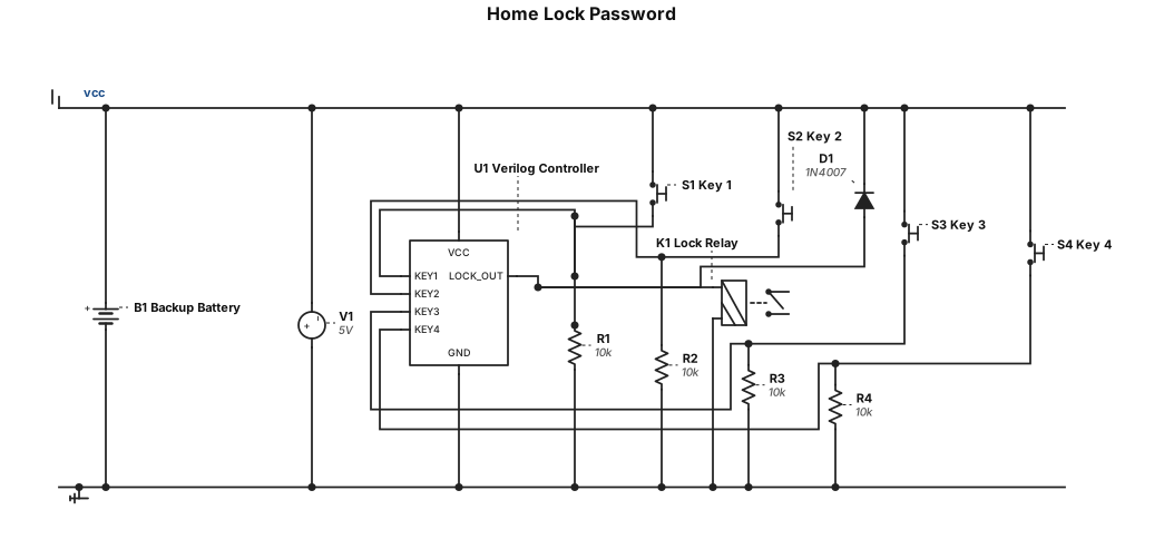
Make circuit for home lock password by verilog without arduino
ENGINEERING DRAWING ARCHIVE · REAL SPECS
Engineering Diagram Examples from Real Specifications
Browse eligible circuit, ladder, single-line, P&ID, breadboard, timing, and logic drawings with their original prompts.
Browse 538 real creationsCOMMUNITY OUTPUTS · EXACT PROMPTS
Main engineering studio
Showing 1–24 of 379. No stock examples or system defaults. Choose a tool, study a real result, then reopen its prompt as your starting point.
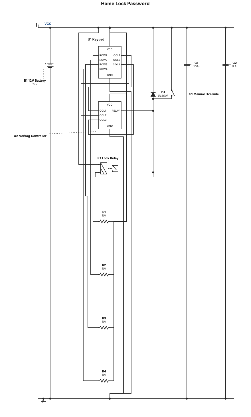
Make circuit for home lock password by verilog
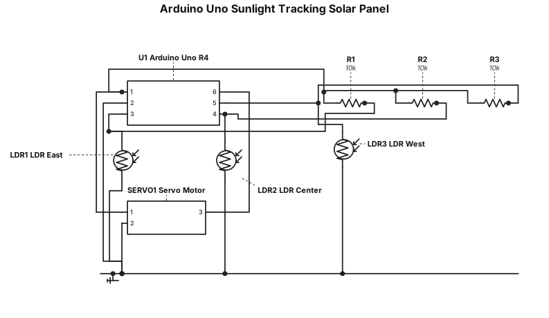
A breadboard wiring diagram for an Arduino Uno a sunlight tracking solar panel made by 3 ldr sensors,1 servo motor and an arduino uno r4
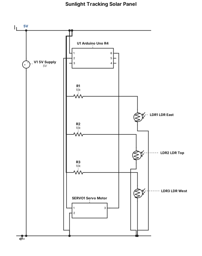
a sunlight tracking solar panel made by 3 ldr sensors,1 servo motor and an arduino uno r4
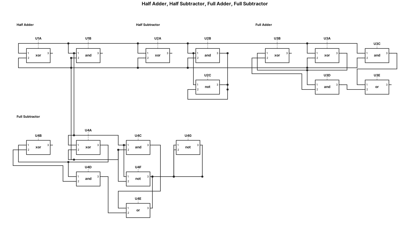
generate the circuit for half adder, half subtracter and full adder , full subtractor make sutre to genrate both by using ics and logic gates
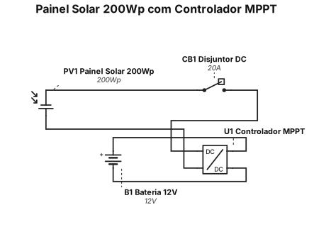
Desenha circuito (colorido)de potência: painel solar 200Wp ligado ao controlador MPPT, com disjuntor DC entre eles.
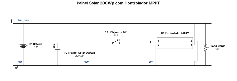
Desenha circuito de potência: painel solar 200Wp ligado ao controlador MPPT, com disjuntor DC entre eles.
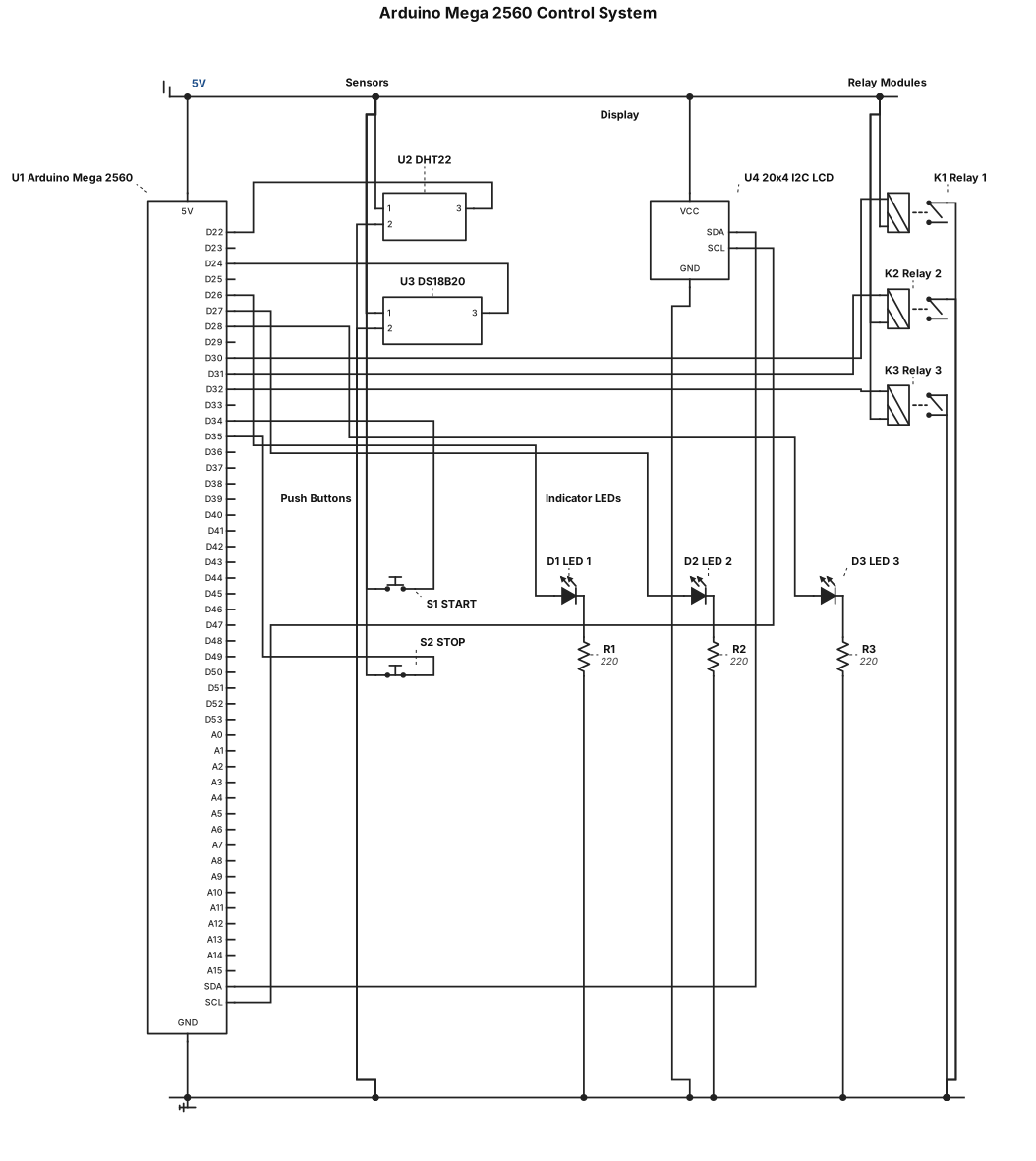
Draw a professional ELECTRONIC CIRCUIT SCHEMATIC, not a mechanical drawing. Use a horizontal landscape layout. Components: 1. Arduino Mega 2560. 2. DHT22 temperature and humidity sensor. 3. DS18B20 temperature sensor. 4. 20x4 I2C LCD. 5. Three relay modules. 6. START push button. 7. STOP push button. 8. Three indicator LEDs. Show the Arduino in the center and arrange all components around it. Draw actual electrical wires connecting the components. Clearly identify Arduino pins, VCC, GND, SDA, SCL and signal connections. Use standard electronic symbols. Make all labels large and readable. Do not draw the dryer cabinet, trays, mechanical dimensions or 3D objects. Output one clean electronic schematic diagram.

Create an Arduino Mega 2560 electronic control circuit for an automatic agricultural dryer. Include: - Arduino Mega 2560 - DHT22 humidity and temperature sensor - DS18B20 temperature sensor - 20x4 LCD with I2C module - Three relay modules - Two push buttons (START and STOP) - Three indicator LEDs - Appropriate resistors Connect all components to the Arduino Mega 2560. The Arduino must read temperature and humidity, display the measurements on the LCD and control three relay outputs. Show all component symbols, pin numbers, power connections and signal connections. Generate a clear electronic schematic diagram.
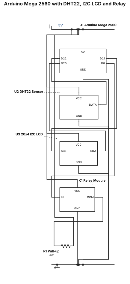
Create a simple Arduino Mega 2560 circuit with a DHT22 temperature and humidity sensor, a 20x4 I2C LCD and one relay module. Connect all components and show the wiring diagram with pin labels.
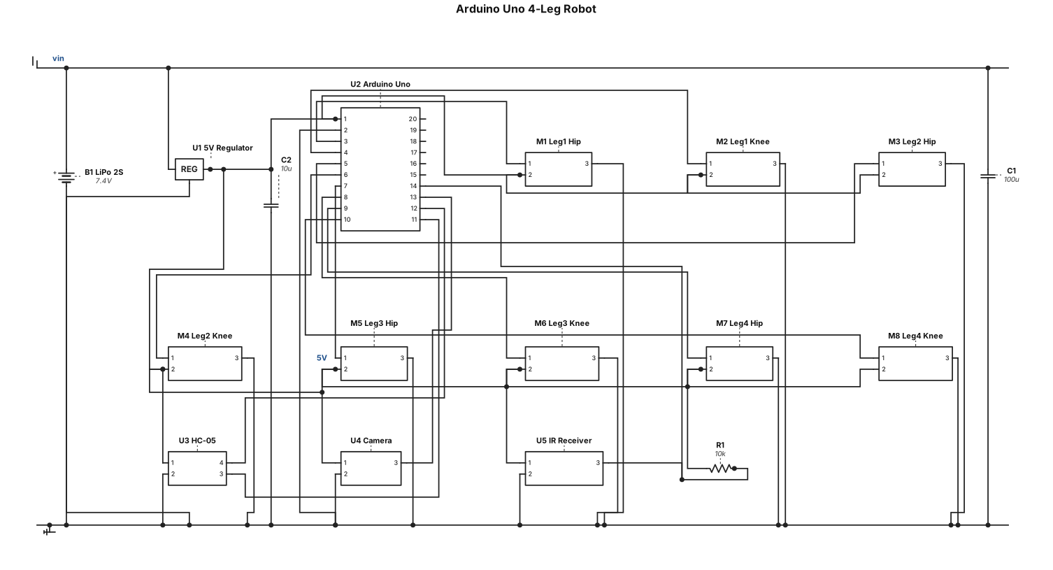
A 5v Arduino uno robot, with 4 legs with 2 servos each and a camera on top, wich needs to connect via bluetooth, with an infra red sensor to turn on/off with a remote
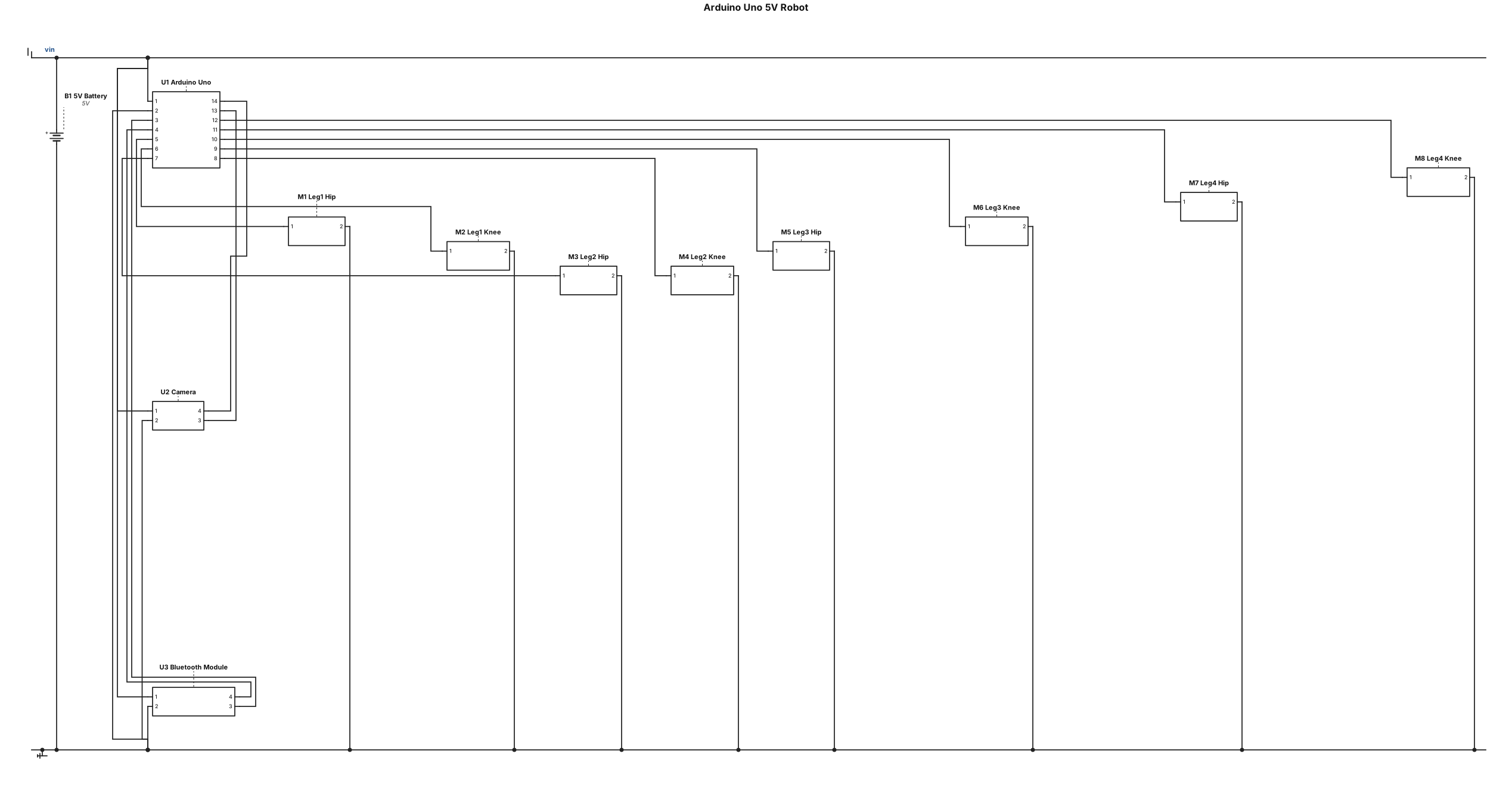
A 5v Arduino uno robot, with 4 legs with 2 servos each and a camera on top, wich needs to connect via bluetooth
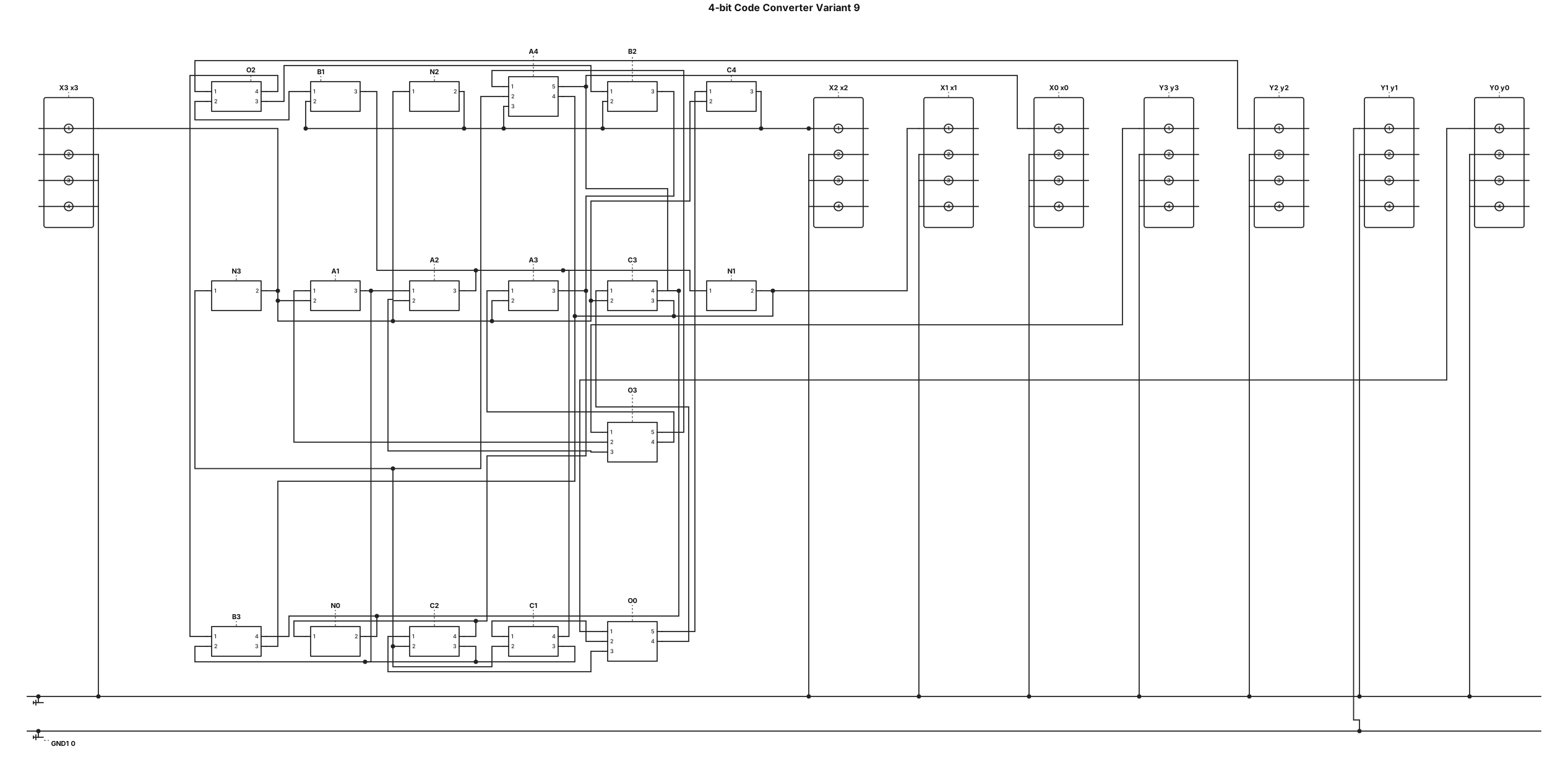
Draw a combinational logic gate diagram for a 4-bit code converter, Variant 9. Use ONLY NOT, AND and OR gates. Use multi-input gates as specified below. Do not use XOR, XNOR, NAND, NOR, multiplexers, memory, counters or a DAC. Do not simplify or change the specified netlist. Inputs on the left: x3, x2, x1, x0 (x3 is MSB). Outputs on the right: y3, y2, y1, y0 (y3 is MSB). Create four shared NOT gates: N3: nx3 = NOT(x3) N2: nx2 = NOT(x2) N1: nx1 = NOT(x1) N0: nx0 = NOT(x0) AND gates for y3: A1 = AND(x3, nx2) A2 = AND(x3, nx1) A3 = AND(x3, nx0) A4 = AND(nx3, x2, x1, x0) O3: y3 = OR(A1, A2, A3, A4) AND gates for y2: B1 = AND(x2, nx1) B2 = AND(x2, nx0) B3 = AND(nx2, x1, x0) O2: y2 = OR(B1, B2, B3) y1 = constant logic 0. Show a direct connection from a logic-0 symbol to y1, without any gate. AND gates for y0: C1 = AND(nx3, nx2, nx1) C2 = AND(nx3, nx2, nx0) C3 = AND(x3, x1, x0) C4 = AND(x3, x2) O0: y0 = OR(C1, C2, C3, C4) Layout: inputs and shared inverters on the left, AND gates in the middle, OR gates and outputs on the right. Arrange output sections vertically: y3, y2, y1, y0. Show every gate and its label. Use clear orthogonal wires, junction dots only at connected crossings, and no dots at unconnected crossings. Use labeled nets if needed to avoid clutter. Never join different output nets. Expected total: 4 NOT gates, 11 AND gates, 3 OR gates = 18 logic gates. The logic-0 symbol is not a gate.
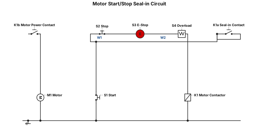
A PLC ladder diagram for a motor start/stop seal-in circuit with an emergency-stop interlock and an overload contact.
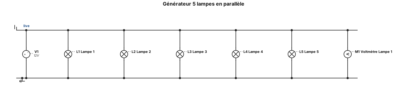
1 générateur 5 lampe en parallèle un voltmètre sur la lampe 1
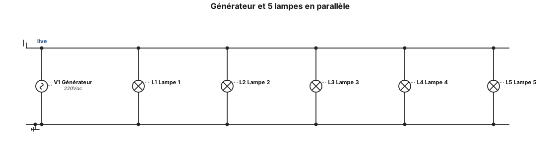
1 générateur 5 lampe en parallèle
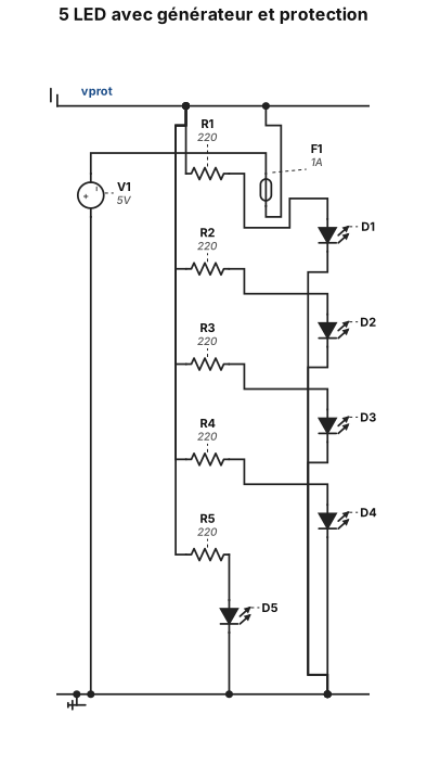
5 led un générateur une protection
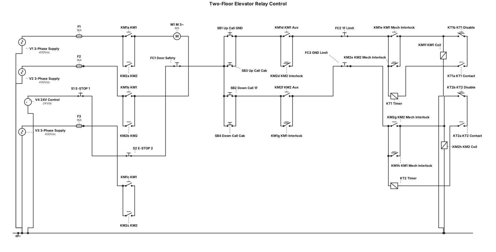
Create a complete electrical control and power schematic for a two-floor elevator, using wired relay logic, NOT PLC. Follow the layout of the uploaded reference drawing. Requirements: - 24V control circuit. - Three-phase motor. - KM1 for upward movement. - KM2 for downward movement. - Electrical and mechanical interlocking. - FC1 door safety limit switch. - FC2 first-floor limit switch. - FC3 ground-floor limit switch. - Internal and external call pushbuttons. - Two emergency stop buttons. - Two independent 5-second ON-delay timers (KT1 and KT2). - When the elevator reaches the first floor, FC2 stops KM1 immediately and activates KT1 for 5 seconds, simulating door opening. - When the elevator reaches the ground floor, FC3 stops KM2 immediately and activates KT2 for 5 seconds. - During each 5-second interval, both motor contactors must remain disabled. - After 5 seconds, the elevator remains stopped and waits for a new call. - Include the complete control circuit and three-phase power circuit. - Use IEC electrical symbols and clear component labels. - Do not use PLCs.
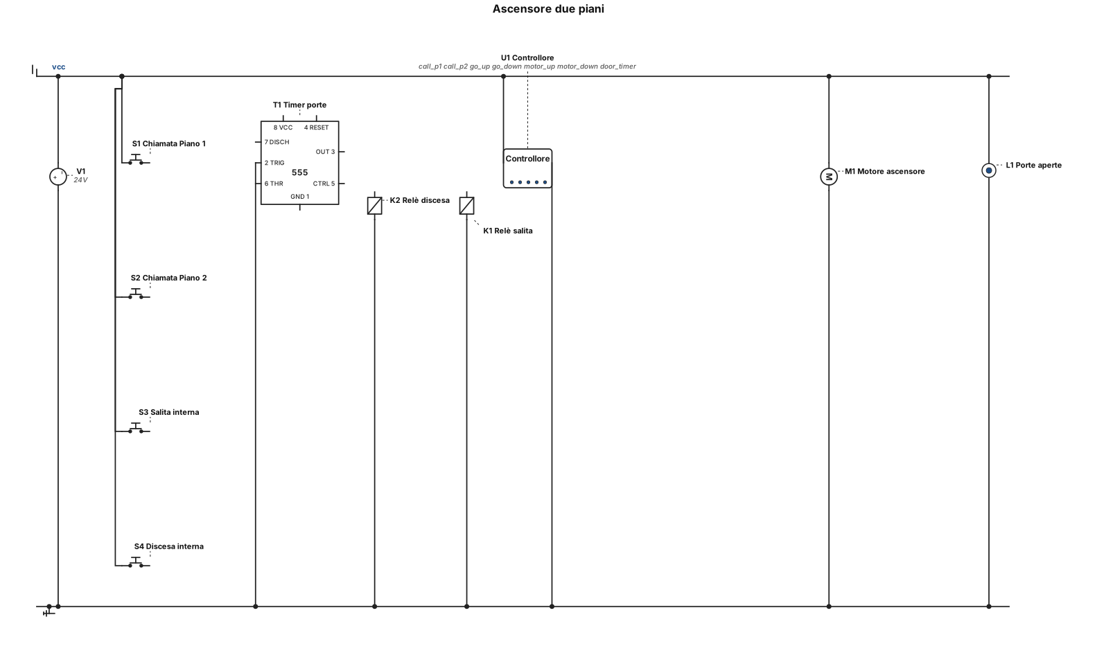
ascensore due piani con due pulsanti esterni che chiamano l'ascensore e due pulsanti interni per far salire e scendere l'ascensore. quando arriva al piano deve partire un temporizzatore che blocca l'ascensore simulando l'apertura delle porte.
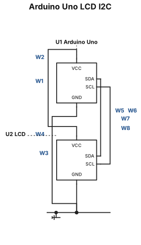
Connect the LCD's GND pin to the Arduino Uno's GND pin and its VCC pin to the 5V pin. Connect the LCD's SDA pin to Analog Pin A4 for I2C data communication and the SCL pin to Analog Pin A5 for I2C clock communication.
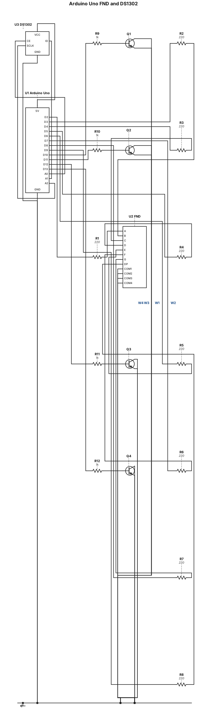
Connect FND Pin 11 (A) to Digital Pin 2, FND Pin 7 (B) to Digital Pin 3, FND Pin 4 (C) to Digital Pin 4, FND Pin 2 (D) to Digital Pin 5, FND Pin 1 (E) to Digital Pin 6, FND Pin 10 (F) to Digital Pin 7, FND Pin 5 (G) to Digital Pin 8, and FND Pin 3 (DP) to Digital Pin 9 of the Arduino Uno, using a 220Ω resistor for each connection. Connect FND Pins 12 (COM1), 9 (COM2), 8 (COM3), and 6 (COM4) to Digital Pins 10, 11, 12, and 13, respectively, through 1KΩ resistors connected to the transistor bases. Connect each transistor's emitter to GND and collector to its corresponding FND common pin.  Connect the DS1302 module's VCC to 5V and GND to GND. Connect its CE (RST) pin to Analog Pin A0, I/O (DAT) to Analog Pin A1, and SCLK (CLK) to Analog Pin A2 of the Arduino Uno.
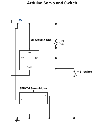
Connect the servo motor's orange signal wire to Digital Pin 9 of the Arduino Uno, the red VCC wire to the 5V pin, and the brown GND wire to GND. Connect one leg of the switch to Digital Pin 2 and the other leg to GND. Connect a 10KΩ pull-up resistor between the 5V pin and Digital Pin 2, with one end connected to 5V and the other end connected to Digital Pin 2.
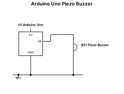
Connect the positive (+) terminal of the piezo buzzer to Digital Pin 8 of the Arduino Uno using a jumper wire. Connect the negative (−) terminal of the buzzer directly to the GND pin of the Arduino Uno.
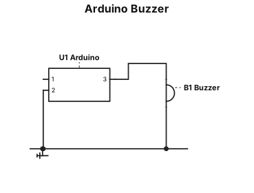
| Buzzer (+) to arduino Digital Pin 8 | | Buzzer (-) arduino Pin GND using my labels intatct