
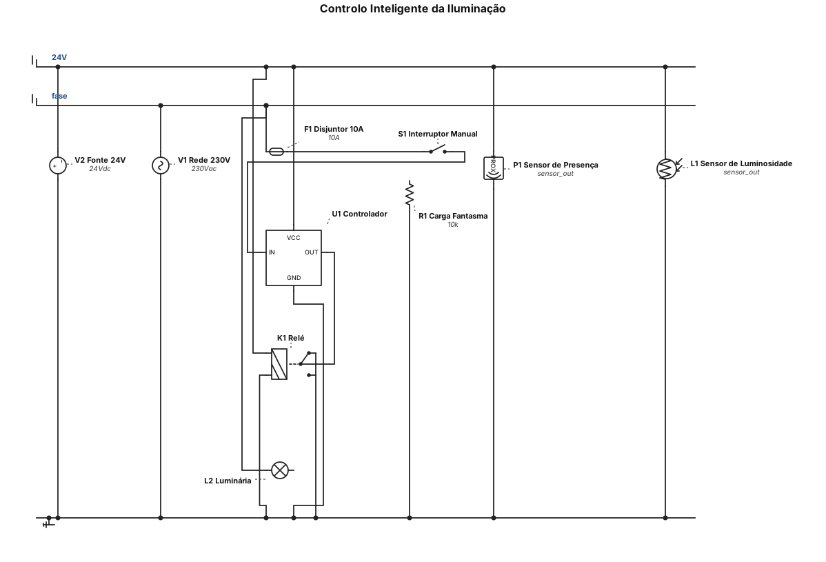
Controlo inteligente da iluminação com uso de sensoress de presença e luminosidade para um condomínio residencial
ENGINEERING DRAWING ARCHIVE · REAL SPECS
Engineering Diagram Examples from Real Specifications
Browse eligible circuit, ladder, single-line, P&ID, breadboard, timing, and logic drawings with their original prompts.
Browse 546 real creationsCOMMUNITY OUTPUTS · EXACT PROMPTS
All visitor creations
Showing 241–264 of 546. No stock examples or system defaults. Choose a tool, study a real result, then reopen its prompt as your starting point.
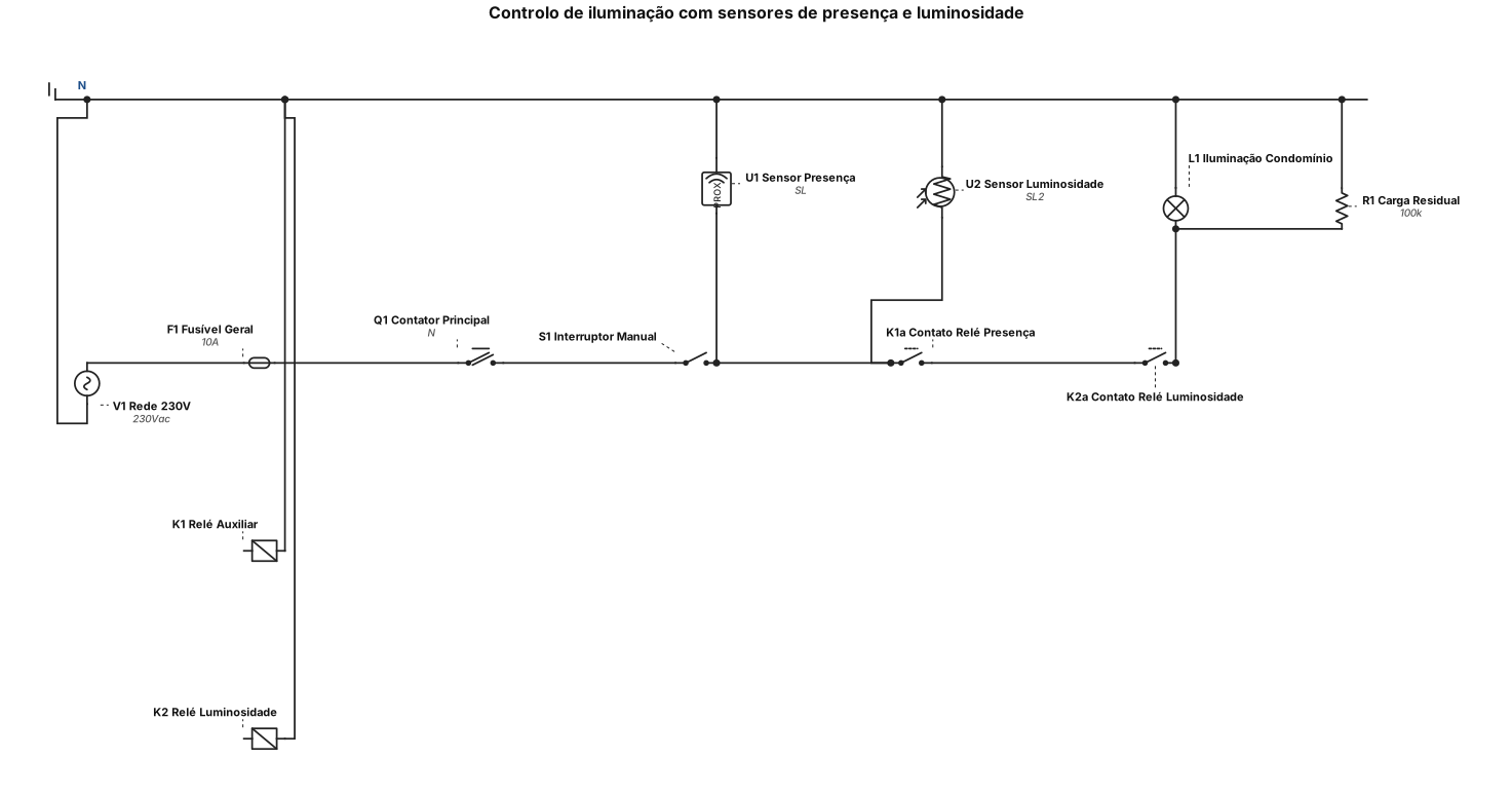
Circuito de comando e de potência para o Controlo de iluminação com uso de sensores de presença e luminosidade para um condomínio residencial
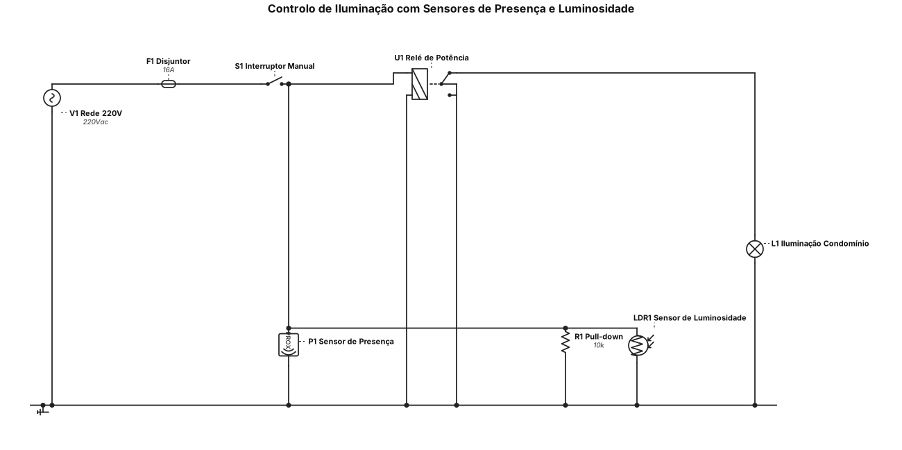
Controlo de iluminação com uso de sensores de presença e luminosidade para um condomínio residencial
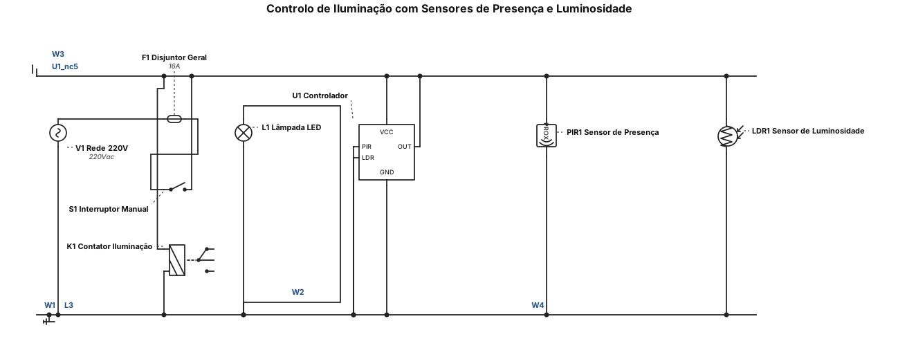
Controlo de iluminação com uso de sensoress de presença e luminosidade para um condomínio residencial
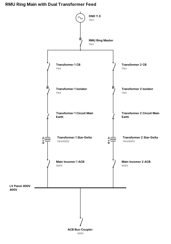
there is a RMU ring master being feed by the DNO marked as Y.E this is in the open position this feeds transformer 1 CB which is in the open position feeding another transformer isolator which is in the open position and in main circuit earth and transformer 2 which is in the open position and in circuit main earth both transformer are star delta 11 kV, feeding a 400V LV panel which protected by 2 ACBs, main incomer 1 and main incomer 2 both in the open position with a ACB bus-coupler also in the open position. points of isolation at all ACB's and the the circuit main earth positions
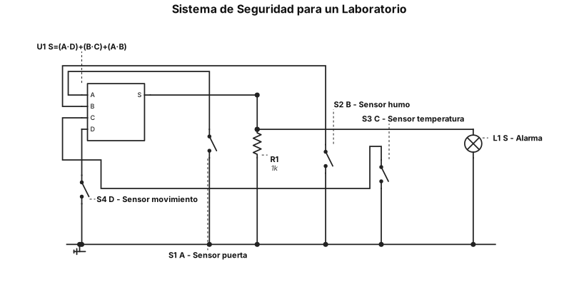
Sí. En las imágenes que me enviaste, la actividad dice esto: Sistema de Seguridad para un Laboratorio Entradas: - A — Sensor puerta - 1 = Puerta abierta - 0 = Puerta cerrada - B — Sensor humo - 1 = Detecta humo - 0 = No detecta humo - C — Sensor temperatura - 1 = Temperatura elevada - 0 = Temperatura normal - D — Sensor de movimiento - 1 = Detecta movimiento - 0 = No detecta movimiento Salida: - S — Alarma - 1 = Activa - 0 = Inactiva Cuándo encender la alarma La pizarra indica que la alarma debe encenderse cuando: I) Puerta abierta y detecta movimiento. II) Presencia de humo y temperatura elevada. III) Puerta abierta y presencia de humo, independientemente de los otros sensores. En cualquier otro caso, la alarma debe permanecer apagada. Y finalmente pide: i) Determinar la función lógica para la salida y validarla en una calculadora de mapas. ii) Implementarla y simularla en Tinkercad. Por eso, la función que corresponde es: \[ \boxed{S=(A\cdot D)+(B\cdot C)+(A\cdot B)} \] La primera imagen muestra además que después deben pasar esa tabla de verdad a un mapa de Karnaugh.
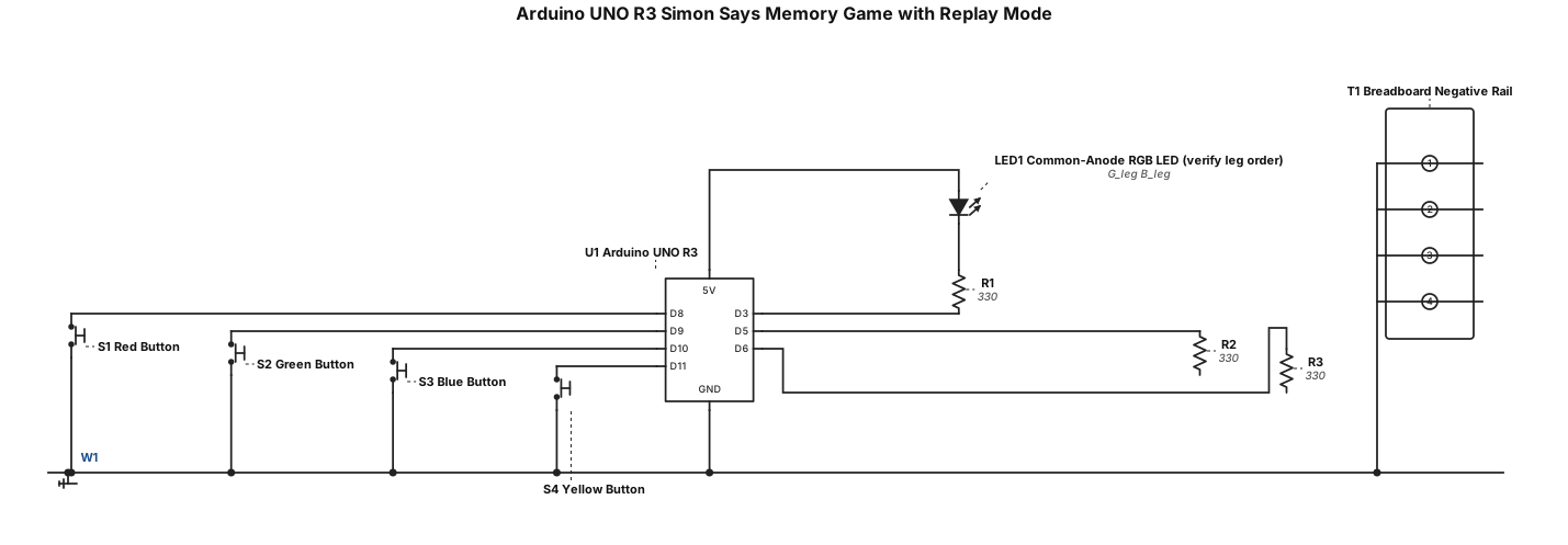
Create a clear, accurate breadboard wiring diagram for an Arduino UNO R3 Simon Says memory game with replay mode. Use one common-anode 4-pin RGB LED, four push buttons, three 330-ohm resistors, a breadboard, and jumper wires. Connect the LED's common-anode leg to 5V. Connect its red, green, and blue colour legs through separate 330-ohm resistors to Arduino pins D3, D5, and D6, respectively. Connect the red, green, blue, and yellow buttons to D8, D9, D10, and D11, respectively. Connect the opposite terminal of each button to GND. Use INPUT_PULLUP, so no extra button resistors are required. Connect Arduino GND to the breadboard's negative rail. Label all pins, components, and connections. Use a neat top-down view, with every wire ending at the correct pin or breadboard row. Do not invent the RGB LED's physical leg order; label each leg by function and show that the exact leg positions must be verified.
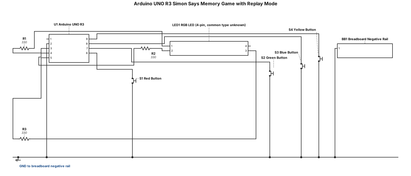
Create a clear, accurate wiring diagram for an Arduino UNO R3 Simon Says memory game with replay mode. Show one 4-pin RGB LED, four push buttons, three 330-ohm resistors, a breadboard, and jumper wires. Connect the LED red, green, and blue channels through separate resistors to pins D3, D5, and D6. Connect the red, green, blue, and yellow buttons to D8, D9, D10, and D11, respectively. Connect the other side of every button to GND. Use INPUT_PULLUP, so no button resistors are needed. Connect Arduino GND to the breadboard's negative rail. Label every pin and wire clearly. Do not guess the RGB LED's leg order or common-pin type; mark them as unknown until verified. Use a clean top-down view and ensure every wire connects to the correct point.
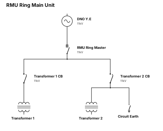
there is a RMU ring master being feed by the DNO marked as Y.E this is in the open position this feeds transformer 1 CB which is in the open position and transformer 2 which is in the open position and in circuit earth

b) Design and implement a 4 bit Logic unit using a MUX. AND, OR, XOR, NOT ehre is the gates
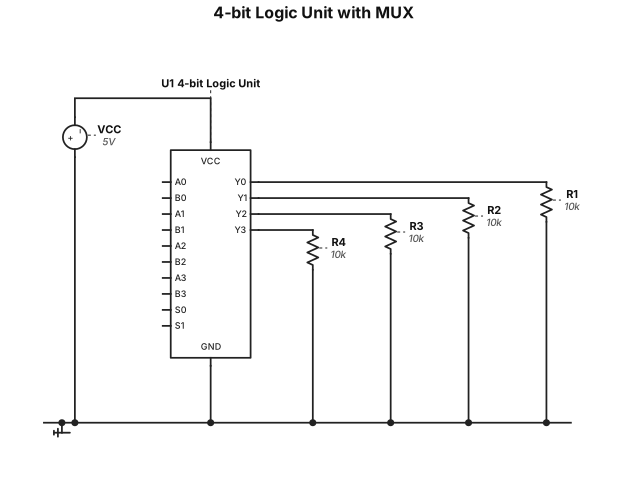
b) Design and implement a 4 bit Logic unit using a MUX. AND, OR, XOR, NOT
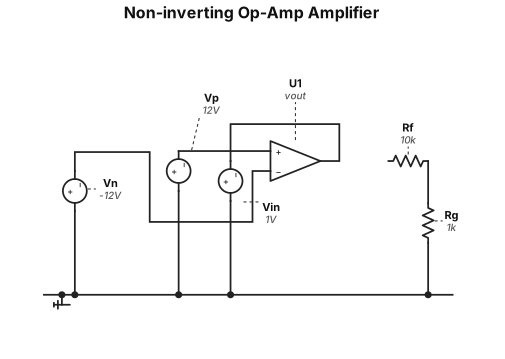
A non-inverting op-amp amplifier powered from plus and minus 12 V, with gain 11 using a 10 kilohm feedback resistor and 1 kilohm resistor to ground.
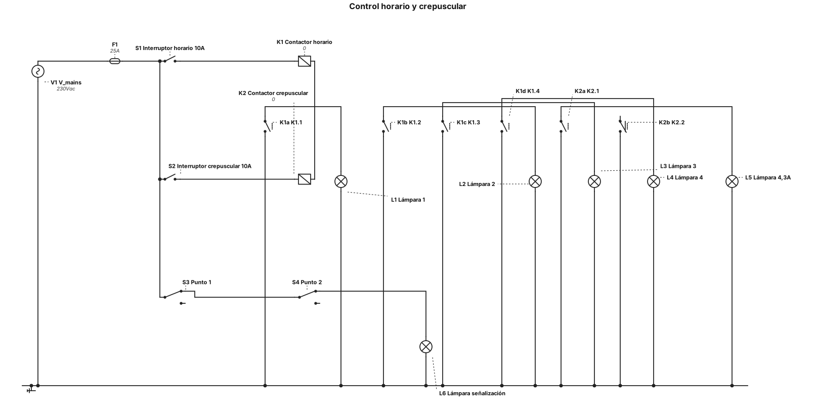
En una instalación eléctrica un interruptor horario de 10 A debe accionar 4 lámparas con un consumo total de 18 A, y por otra parte, un interruptor crepuscular de 10 A debe accionar una lámpara de 4,3 A cuando no haya luz solar, y una lámpara de señalización cuando haya luz solar. Esta última también se puede encender a través desde 2 puntos con mecanismos manuales.
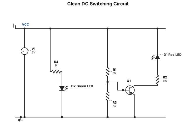
Clean DC switching circuit: A 5V DC power source (V1) with its positive terminal connected to a common VCC rail and negative to ground (GND). A 3 kΩ resistor (R1) connected in series from VCC to the base of an NPN transistor (Q1). The collector of Q1 is connected through a 10 kΩ resistor (R2) and a red LED (D1) in series back to VCC. A 5 kΩ resistor (R3) connected from the base of Q1 to ground. The emitter of Q1 is connected directly to ground. A green LED (D2) connected in series with its protection resistor from VCC to ground. the circuit has a cos φ of 1.5
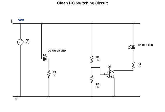
Clean DC switching circuit: A 5V DC power source (V1) with its positive terminal connected to a common VCC rail and negative to ground (GND). A 3 kΩ resistor (R1) connected in series from VCC to the base of an NPN transistor (Q1). The collector of Q1 is connected through a 10 kΩ resistor (R2) and a red LED (D1) in series back to VCC. A 5 kΩ resistor (R3) connected from the base of Q1 to ground. The emitter of Q1 is connected directly to ground. A green LED (D2) connected in series with its protection resistor from VCC to ground.
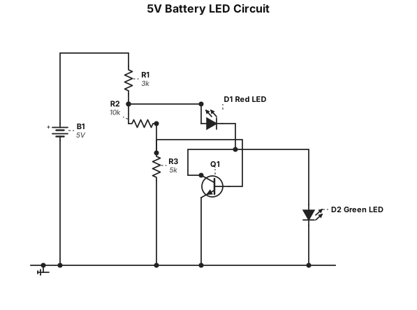
A circuit powered by a 5V battery, featuring a 3-kiloohm resistor, a 10-kiloohm resistor, a 5-kiloohm resistor, an NPN transistor, a red LED, and a green LED; the circuit has a cos φ of 1.5.
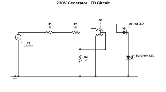
A circuit powered by a 230V generator, comprising a 3 kΩ resistor, a 10 kΩ resistor, a 5 kΩ resistor, an NPN transistor, a red LED, and a green LED; the circuit has a cos φ of 1.5.
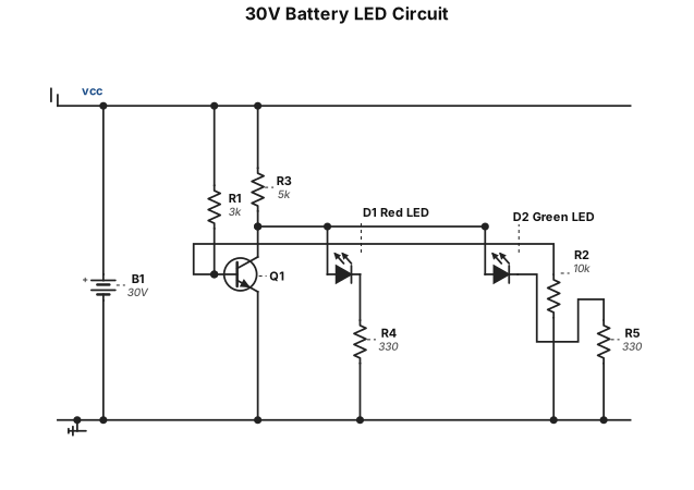
A circuit powered by a 30V battery, featuring a 3 kΩ resistor, a 10 kΩ resistor, a 5 kΩ resistor, an NPN transistor, a red LED, and a green LED; the circuit has a cos φ of 1.5.
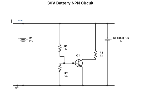
A circuit powered by a 30V battery, featuring a 3-kiloohm resistor, a 10-kiloohm resistor, a 5-kiloohm resistor, and an NPN transistor; the circuit has a cos φ of 1.5.
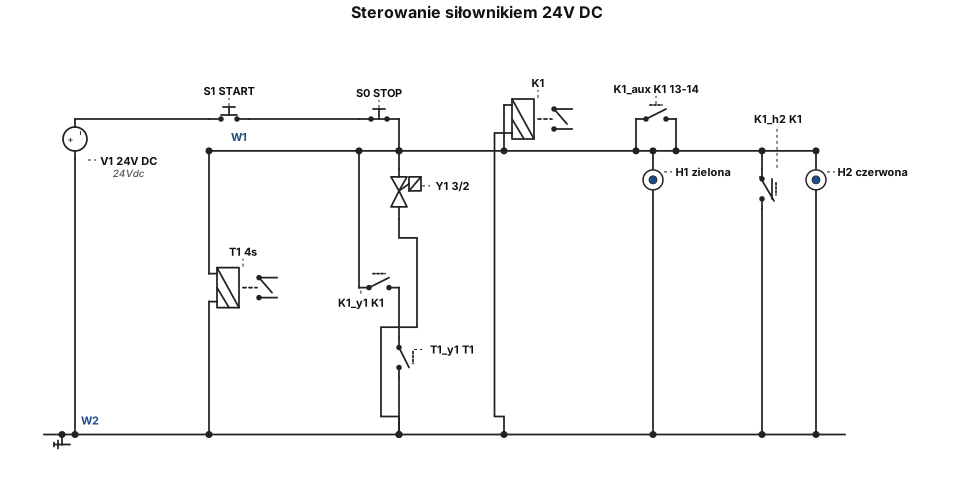
Narysuj profesjonalny, czytelny schemat elektryczny w standardzie przemysłowym IEC, w formie drabinkowej LADDER. Elementy układu: - S1 — przycisk START NO - S0 — przycisk STOP NC - K1 — przekaźnik z podtrzymaniem przez styk pomocniczy NO 13-14 - T1 — przekaźnik czasowy ustawiony na 4 sekundy - Y1 — cewka elektrozaworu 3/2 z powrotem sprężynowym - H1 — lampka sygnalizacyjna zielona - H2 — lampka sygnalizacyjna czerwona - Zasilanie sterowania 24 V DC Zasada działania: 1. Po krótkim naciśnięciu START układ uruchamia się i przekaźnik K1 podtrzymuje się. 2. Elektrozawór Y1 włącza się i siłownik jednostronnego działania wysuwa się. 3. Podczas wysuwania świeci zielona lampka H1, a czerwona H2 jest wyłączona. 4. Po 4 sekundach układ wyłącza Y1. Zawór wraca sprężyną i siłownik chowa się. 5. Gdy siłownik jest w pozycji spoczynkowej, zielona lampka H1 jest wyłączona, a czerwona H2 świeci. 6. Przycisk STOP wyłącza układ. Wykonaj osobne linie drabinkowe dla przekaźnika, podtrzymania, czasówki, elektrozaworu oraz obu lampek. Zieloną lampkę podłącz tak, aby świeciła podczas zasilania cewki Y1. Czerwoną lampkę podłącz przez odpowiedni styk przekaźnika, aby świeciła w stanie spoczynkowym, a gasła podczas wysuwania. Zastosuj symbole IEC, numery styków, oznaczenia przewodów i czytelne opisy. Uporządkuj schemat symetrycznie, bez krzyżujących się przewodów. Nie twórz schematu blokowego. Sprawdź poprawność logiczną układu.
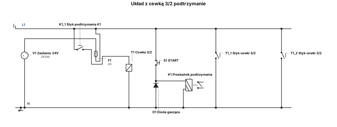
Zbuduj mi układ elektryczny z cewką 3/2 przekaźnikiem który musi być podtrzymany . Z czasówką i przyciskiem Który na starcie aktywuje cały program
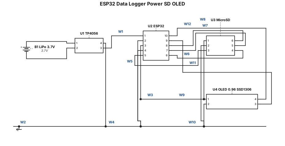
1. Power & Charging Subsystem (TP4056 & Battery)3.7V LiPo Battery Positive (+) $\rightarrow$ TP4056 B+ pad3.7V LiPo Battery Negative (-) $\rightarrow$ TP4056 B- padTP4056 OUT+ (Power Output) $\rightarrow$ ESP32 VIN (or 5V) pinTP4056 OUT- (Ground Output) $\rightarrow$ ESP32 GND pinNote: Recharging is handled via the onboard Type-C port on the TP4056 module.2. MicroSD Card Module (SPI Interface)VCC $\rightarrow$ ESP32 3V3 pinGND $\rightarrow$ ESP32 GND pinCS (Chip Select) $\rightarrow$ ESP32 GPIO 5 (labeled D5)SCK (Serial Clock) $\rightarrow$ ESP32 GPIO 18 (labeled D18)MISO (Master In Slave Out) $\rightarrow$ ESP32 GPIO 19 (labeled D19)MOSI (Master Out Slave In) $\rightarrow$ ESP32 GPIO 23 (labeled D23)3. OLED Display (0.96" SSD1306, I2C Interface)VCC $\rightarrow$ ESP32 3V3 pinGND $\rightarrow$ ESP32 GND pinSCL (Serial Clock) $\rightarrow$ ESP32 GPIO 22SDA (Serial Data) $\rightarrow$ ESP32 GPIO 21
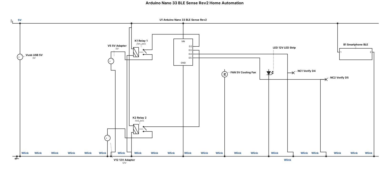
Draw an actual electronic wiring diagram for an Arduino Nano 33 BLE Sense Rev2 home automation project. Connect Arduino GPIO pins to a 4-channel 5V relay module. Use relay channel 1 to switch a 5V cooling fan powered by a 5V adapter, and relay channel 2 to switch a 12V LED strip powered by a separate 12V adapter. Show the USB cable powering the Arduino and a smartphone communicating wirelessly over BLE. Draw real wires between component pins and relay terminals, and label GPIO, IN1, IN2, VCC, GND, COM, NO, positive and negative terminals. Keep the 5V and 12V circuits separate. Do not invent unknown pin connections; mark them for verification. Show a practical electrical schematic, not a block diagram.
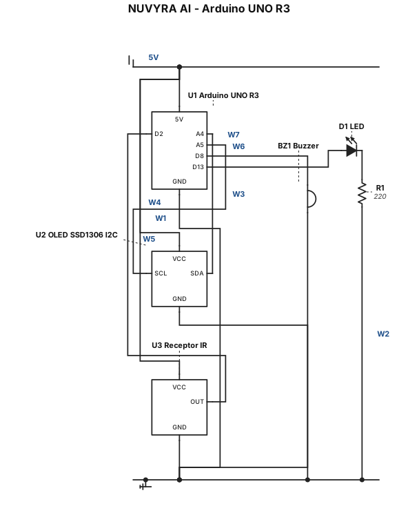
Genera un esquema eléctrico claro y de alta resolución para mi proyecto NUVYRA AI con Arduino UNO R3, pantalla OLED SSD1306 I2C, receptor infrarrojo para control remoto, buzzer y LED con resistencia de 220 ohmios. Etiqueta cada pin y cada cable. OLED: SDA a A4 y SCL a A5. Receptor infrarrojo: señal a D2. Buzzer positivo a D8 y negativo a GND. LED controlado por D13 con resistencia de 220 ohmios. Indica las conexiones de alimentación según las especificaciones de cada componente. No inventes conexiones. Organiza los cables por colores y evita que se crucen.