
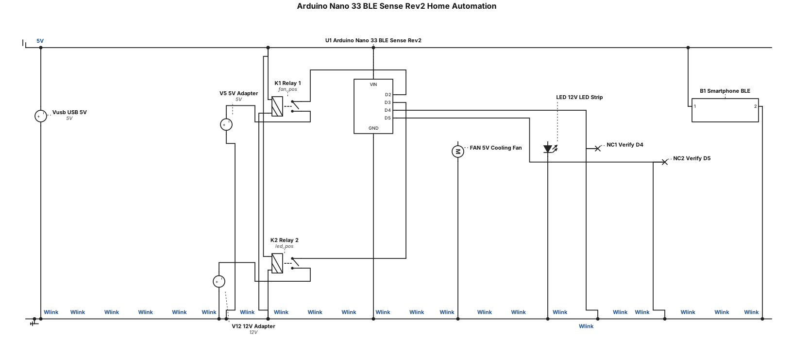
Draw an actual electronic wiring diagram for an Arduino Nano 33 BLE Sense Rev2 home automation project. Connect Arduino GPIO pins to a 4-channel 5V relay module. Use relay channel 1 to switch a 5V cooling fan powered by a 5V adapter, and relay channel 2 to switch a 12V LED strip powered by a separate 12V adapter. Show the USB cable powering the Arduino and a smartphone communicating wirelessly over BLE. Draw real wires between component pins and relay terminals, and label GPIO, IN1, IN2, VCC, GND, COM, NO, positive and negative terminals. Keep the 5V and 12V circuits separate. Do not invent unknown pin connections; mark them for verification. Show a practical electrical schematic, not a block diagram.
ENGINEERING DRAWING ARCHIVE · REAL SPECS
Engineering Diagram Examples from Real Specifications
Browse eligible circuit, ladder, single-line, P&ID, breadboard, timing, and logic drawings with their original prompts.
Browse 548 real creationsCOMMUNITY OUTPUTS · EXACT PROMPTS
All visitor creations
Showing 265–288 of 548. No stock examples or system defaults. Choose a tool, study a real result, then reopen its prompt as your starting point.
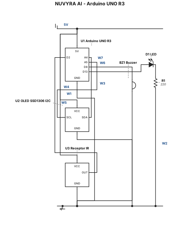
Genera un esquema eléctrico claro y de alta resolución para mi proyecto NUVYRA AI con Arduino UNO R3, pantalla OLED SSD1306 I2C, receptor infrarrojo para control remoto, buzzer y LED con resistencia de 220 ohmios. Etiqueta cada pin y cada cable. OLED: SDA a A4 y SCL a A5. Receptor infrarrojo: señal a D2. Buzzer positivo a D8 y negativo a GND. LED controlado por D13 con resistencia de 220 ohmios. Indica las conexiones de alimentación según las especificaciones de cada componente. No inventes conexiones. Organiza los cables por colores y evita que se crucen.
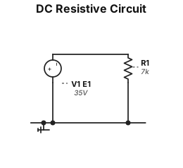
A DC resistive circuit includes a 35 V voltage source, 𝐸1, which supplies a current, 𝐼1, through 1 resistor, 𝑅1, which is 7 kΩ. The negative terminal of the voltage source is at ground.
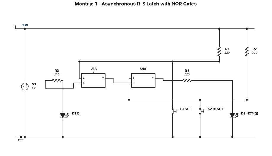
Create an electronic circuit that reproduces Montaje 1 of my Digital Electronics laboratory practice. The circuit is an asynchronous R-S latch using two cross-coupled NOR gates (74LS02). IMPORTANT: Follow the exact component arrangement and electrical connections below. Do not redesign, optimize, simplify, or replace any components. COMPONENTS: - 1 DC power supply: 5 V - 2 NOR gates: U1A and U1B (74LS02) - 2 normally open switches: SET and RESET - 4 resistors: R1, R2, R3, R4, all 220 ohms - 2 LEDs: D1 labeled Q and D2 labeled NOT(Q) - Ground connections INPUT CONNECTIONS: 1. Connect one terminal of the SET switch to GND. 2. Connect the other terminal of SET to the upper input of NOR gate U1A. 3. Connect R1 (220 ohms) between +5 V and the SET input node. 4. Connect one terminal of the RESET switch to GND. 5. Connect the other terminal of RESET to the lower input of NOR gate U1B. 6. Connect R2 (220 ohms) between +5 V and the RESET input node. NOR GATE CONNECTIONS: 7\. Connect the output of U1A to one input of U1B. 8\. Connect the output of U1B to the remaining input of U1A. 9\. Keep both NOR gates cross-coupled to form the R-S latch. OUTPUT CONNECTIONS: 10\. Connect the output of U1A through R3 (220 ohms) to the anode of LED D1 (Q). 11\. Connect the cathode of D1 to GND. 12\. Connect the output of U1B through R4 (220 ohms) to the anode of LED D2 (NOT Q). 13\. Connect the cathode of D2 to GND. LAYOUT: - SET switch at the upper left. - RESET switch at the lower left. - R1 and R2 vertically connected to +5 V. - U1A above U1B in the center. - D1 (Q) to the right of U1A. - D2 (NOT Q) to the right of U1B. - Show the feedback wires clearly between the two NOR gates. - Label all components and values. The final circuit must visually match the reference laboratory schematic as closely as possible. Do not add extra gates, capacitors, clocks, or other components. Make the switches interactive.
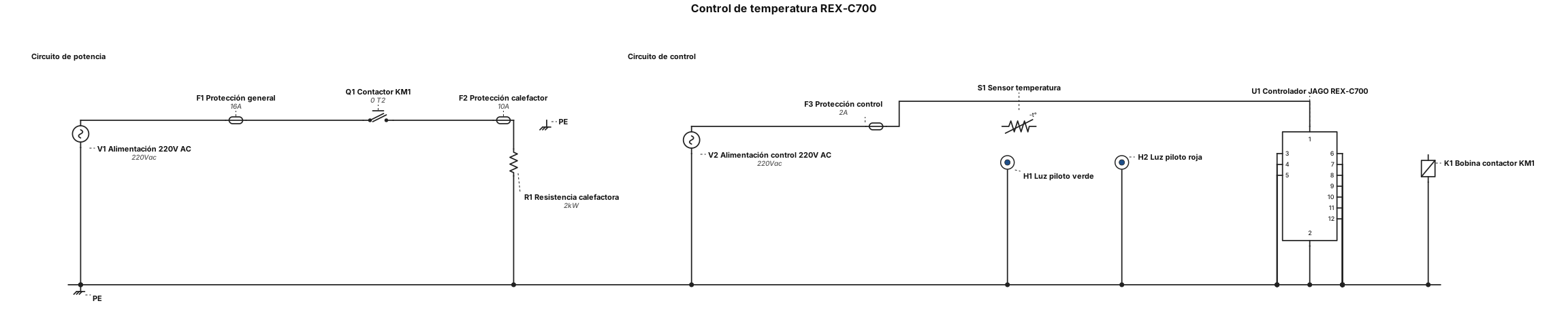
Quiero diseñar un circuito eléctrico de control de temperatura para un proyecto de electromecánica. Necesito que me ayudes a crear el diagrama eléctrico completo, con símbolos normalizados y conexiones claramente identificadas. COMPONENTES 1. Controlador digital de temperatura JAGO REX-C700. 2. Alimentación de 220 V AC. 3. Contactor electromagnético con bobina de 220 V AC. 4. Resistencia calefactora. 5. Sensor de temperatura compatible con el controlador, cuyo tipo está pendiente de confirmar. 6. Una luz piloto verde. 7. Una luz piloto roja. 8. Protecciones eléctricas adecuadas. CIRCUITO DE CONTROL Representa la alimentación del controlador, la conexión del sensor, la salida de control y la bobina del contactor. Verifica los terminales exactos del REX-C700 antes de asignar conexiones. Incluye las dos luces piloto: - Luz verde: debe indicar que la resistencia calefactora está funcionando; preferiblemente, que el contactor está activado. - Luz roja: debe indicar que se alcanzó la temperatura configurada y que la calefacción está detenida. Si estas funciones requieren contactos auxiliares o una configuración específica del controlador, indícalo en el esquema. CIRCUITO DE POTENCIA Representa la alimentación de 220 V AC, las protecciones eléctricas, los contactos principales del contactor y la resistencia calefactora, incluyendo la puesta a tierra correspondiente. PRESENTACIÓN - Separa el circuito de control del circuito de potencia. - Utiliza símbolos eléctricos normalizados. - Identifica los bornes, componentes y conexiones. - Explica el funcionamiento paso a paso. - No inventes terminales ni conexiones del controlador. - Si falta información, pregúntame antes de finalizar el esquema. - Si es posible, genera un diagrama editable y simulable. Quiero un circuito profesional, ordenado y fácil de entender para un estudiante de electromecánica.
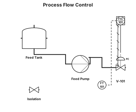
Create a clear p&id with concise labels and the standard notation for this subject.
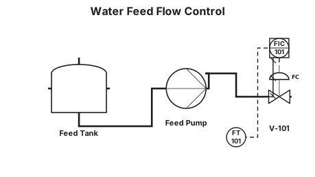
A water feed tank, centrifugal pump, control valve, and outlet line with a flow transmitter sending an electrical signal to a control-room flow controller that pneumatically controls the valve.
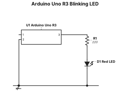
Create a complete and clearly labelled Arduino Uno R3 circuit diagram for a blinking LED experiment, suitable for a beginner's practical exam. Components: Arduino Uno R3, one red LED, one 220-ohm resistor, and jumper wires. Connections: 1. Connect Arduino digital pin 7 to one end of the 220-ohm resistor. 2. Connect the other end of the resistor to the LED's long leg (anode, positive). 3. Connect the LED's short leg (cathode, negative) to Arduino GND. 4. Do not connect the LED directly to 5V; control it using digital pin 7. Expected result: The LED should turn ON for one second and OFF for one second repeatedly. Also provide a visual breadboard-style wiring diagram, labels for every Arduino pin and component, complete Arduino C++ code, simple step-by-step wiring instructions, and a short explanation of how the circuit works.
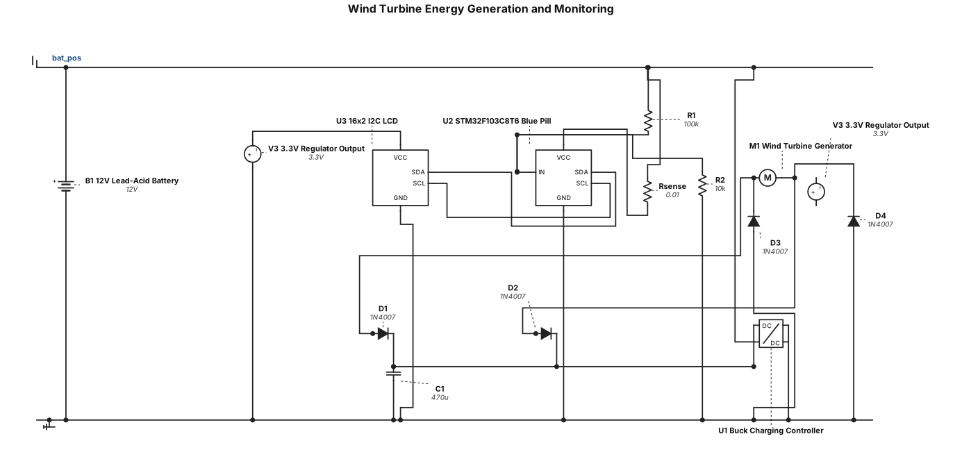
Build a wind turbine energy generation and monitoring project. The system should include: 1. A DC motor used as a wind turbine generator. 2. A bridge rectifier, if required by the generator output. 3. A smoothing capacitor. 4. A DC-DC buck charging controller. 5. A 12V lead-acid battery. 6. A voltage sensor and current sensor. 7. An STM32F103C8T6 Blue Pill microcontroller. 8. A 16x2 I2C LCD display. The STM32 should monitor generator voltage, charging current, output power, and battery voltage, then display the readings on the LCD. Generate the complete circuit schematic with labelled components, pin connections, power rails, and common ground. Use components supported by your simulator and identify any components that cannot be simulated.
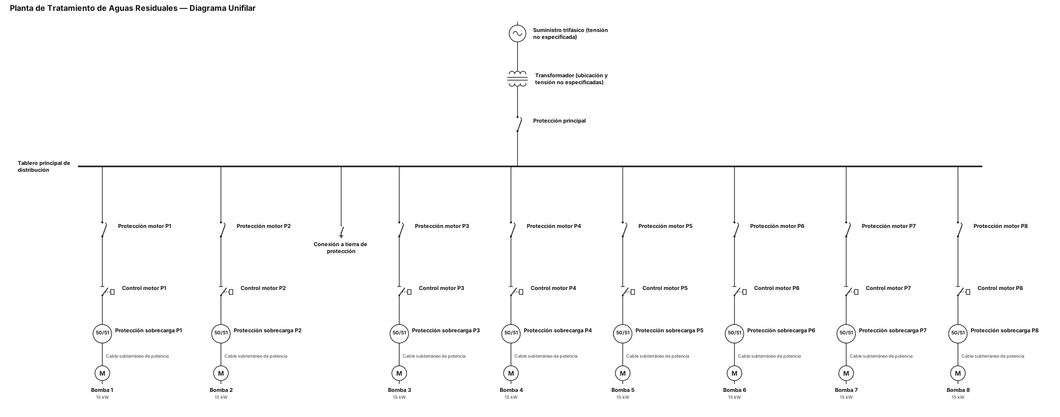
Create a technical single-line electrical diagram for an industrial wastewater treatment plant with eight submersible three-phase pumps, each rated at 15 kW. Include: Three-phase electrical supply. Main protection. Main distribution panel. Eight separate outgoing motor circuits. Individual protection for each pump motor. Motor control equipment for each pump. Underground power cables connecting the circuits to the pumps. Eight motor loads labeled Pump 1 to Pump 8, 15 kW each. Protective earth connections. The problem statement also mentions transformers, control panels, and overload protection. Include these elements only where their connections can be represented without inventing unknown details. Clearly mark the transformer location and electrical supply voltage as unspecified. Use standard electrical single-line diagram symbols, a clean technical layout, and labels in Spanish. Do not invent cable sizes, breaker ratings, transformer ratings, or voltage values.
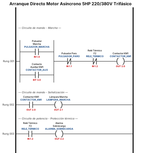
Circuito de mando y potencia de un Arranque directo de un motor asíncrono o de inducción de 5HP 220/380V trifásico.
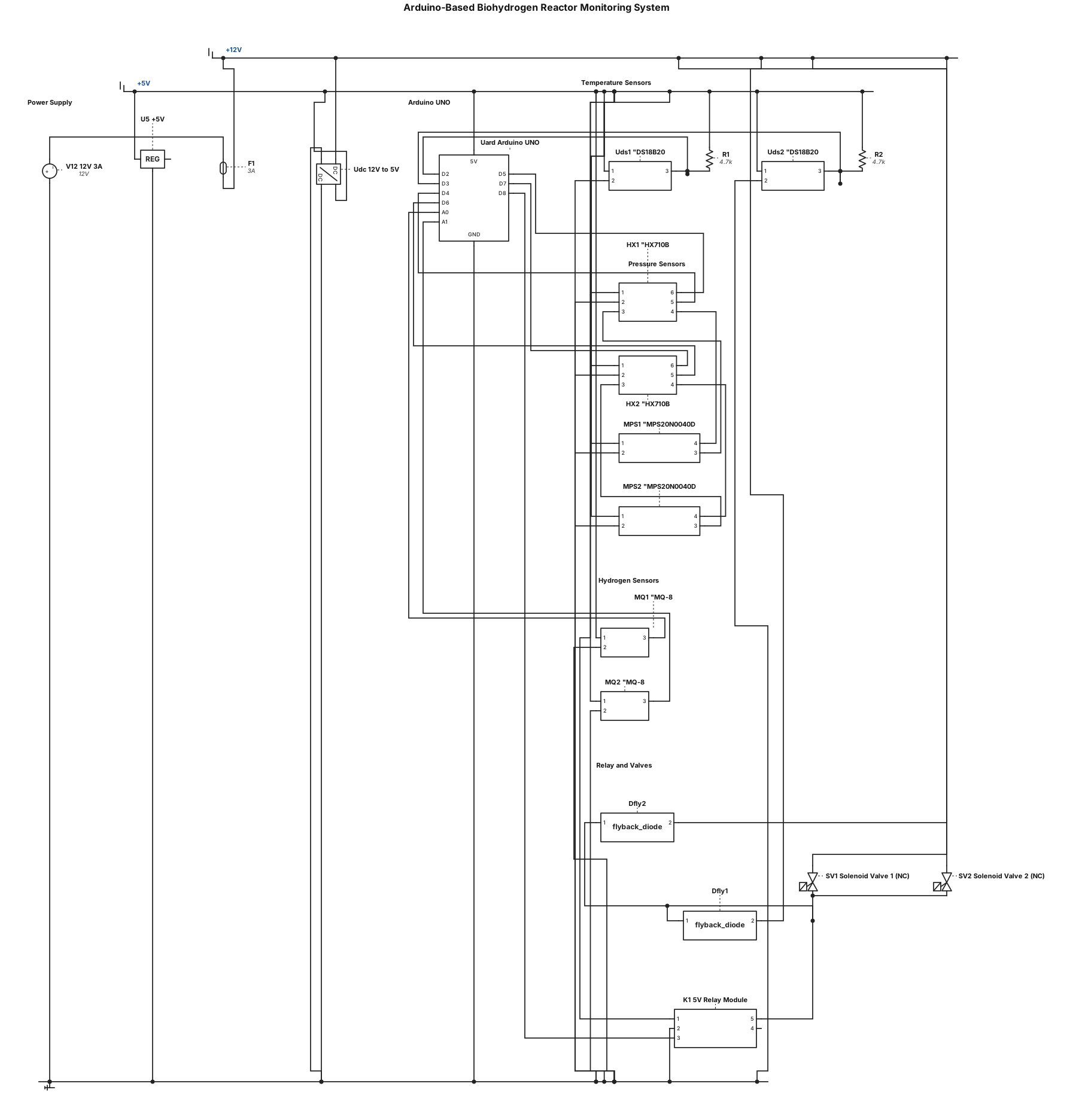
Create a simple conventional electrical schematic on a white background. Use standard electronic symbols, straight horizontal and vertical wires, and clear labels. Do not create an infographic or a realistic drawing. Arrange the circuit in three sections: **LEFT: Power supply** - Place a 12 V, 3 A DC power supply at the bottom left. - Add a 3 A fuse in series with the positive supply. - Place a 12 V to 5 V DC-DC converter next to the supply. - Label the outputs +12 V, +5 V, and GND. **CENTER: Arduino and temperature sensors** - Place an Arduino UNO in the center. - Above it, place two DS18B20 temperature sensors, one above the other. - Connect sensor 1 data to D2 and sensor 2 data to D3. - Add one 4.7 kΩ pull-up resistor from each data line to +5 V. **CENTER-LEFT: Pressure sensors** - Place two MPS20N0040D pressure sensors, one above the other. - Place one HX710B module beside each pressure sensor. - Connect module 1 DT to D4 and SCK to D5. - Connect module 2 DT to D6 and SCK to D7. - Show power and ground connections. Label uncertain sensor terminals "VERIFY PINOUT". **RIGHT: Hydrogen sensors** - Place two MQ-8 modules, one above the other. - Connect the first analog output AO to Arduino A0. - Connect the second analog output AO to Arduino A1. - Connect both modules to +5 V and GND. **BOTTOM-RIGHT: Relay and valves** - Place a 5 V single-channel relay module. - Connect relay IN to Arduino D8. - Place two 12 V, 1 A normally closed solenoid valves to the right of the relay. - Connect both valves in parallel through the relay contacts COM and NO. - Add one flyback diode across each valve, with cathode toward +12 V. Use a common ground reference and label all connections. Keep the drawing simple, organized, and readable. Include the title "Arduino-Based Biohydrogen Reactor Monitoring System". Do not add decorative elements. Do not invent unknown connections. Prioritize a clear electrical schematic over visual detail.
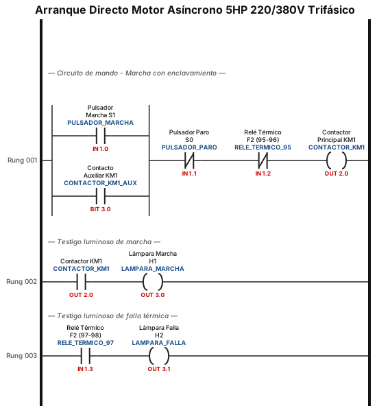
Arranque directo de un motor asíncrono o de inducción de 5HP 220/380V trifásico. El sistema debe tener testigos lumínicos y protecciones (Guardamotor, Termomagnética, fusibles, relee térmico, etc) acorde a la potencia del motor
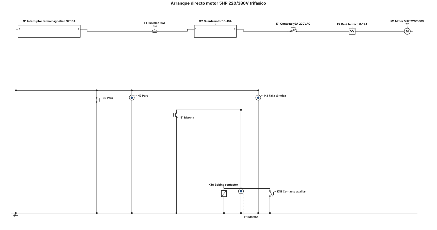
) Grafique un circuito de mando, potencia, y los diagramas Ladder y Bloque para la programación del PLC de los siguientes automatismos, identificando todos los elementos necesarios para realizarlo. Explique detalladamente la lógica de funcionamiento del automatismo mencionando la acción de cada elemento. Realice la simulación en Cadesimu, PC simu o Logo Soft Confort según corresponda a cada clase, y la ejecución en un tablero real. Identificar las características electricas de todos los elementos que intervienen para su selección. Los automatismos son: Arranque directo de un motor asíncrono o de inducción de 5HP 220/380V trifásico. El sistema debe tener testigos lumínicos y protecciones (Guardamotor, Termomagnética, fusibles, relee térmico, etc) acorde a la potencia del motor
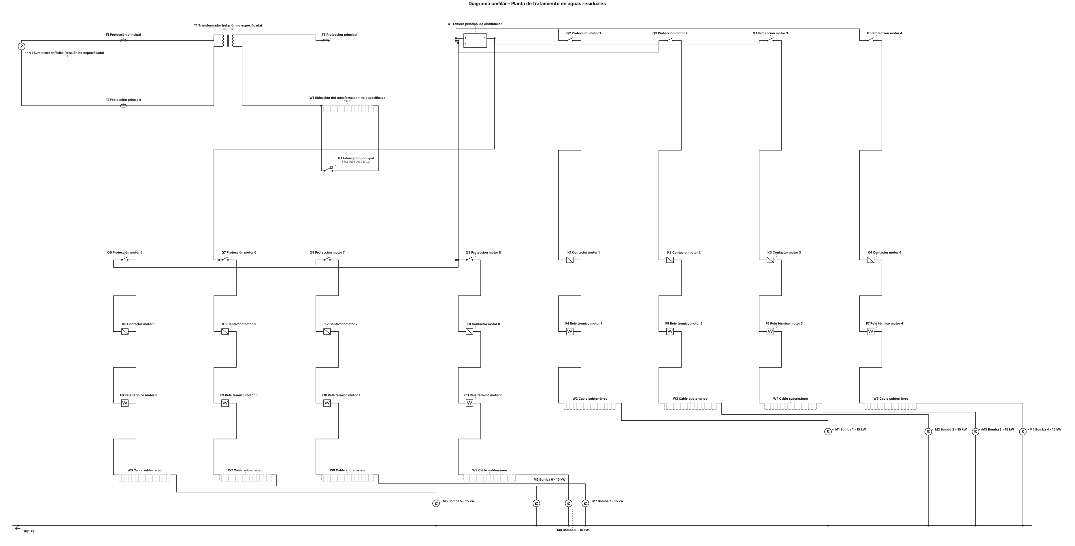
Create a technical single-line electrical diagram for an industrial wastewater treatment plant with eight submersible three-phase pumps, each rated at 15 kW. Include: Three-phase electrical supply. Main protection. Main distribution panel. Eight separate outgoing motor circuits. Individual protection for each pump motor. Motor control equipment for each pump. Underground power cables connecting the circuits to the pumps. Eight motor loads labeled Pump 1 to Pump 8, 15 kW each. Protective earth connections. The problem statement also mentions transformers, control panels, and overload protection. Include these elements only where their connections can be represented without inventing unknown details. Clearly mark the transformer location and electrical supply voltage as unspecified. Use standard electrical single-line diagram symbols, a clean technical layout, and labels in Spanish. Do not invent cable sizes, breaker ratings, transformer ratings, or voltage values.
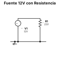
fuente de 12 v, seguido de una resistencia de 220
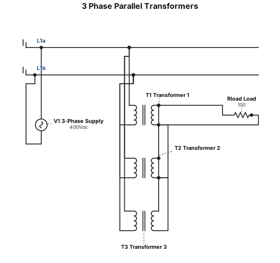
3 phase parallel transformer, transformer 2, and transformer 3
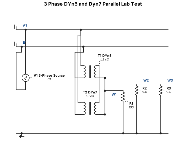
3 phase DYn 5 and Dyn 7 parrallel, tests in lab
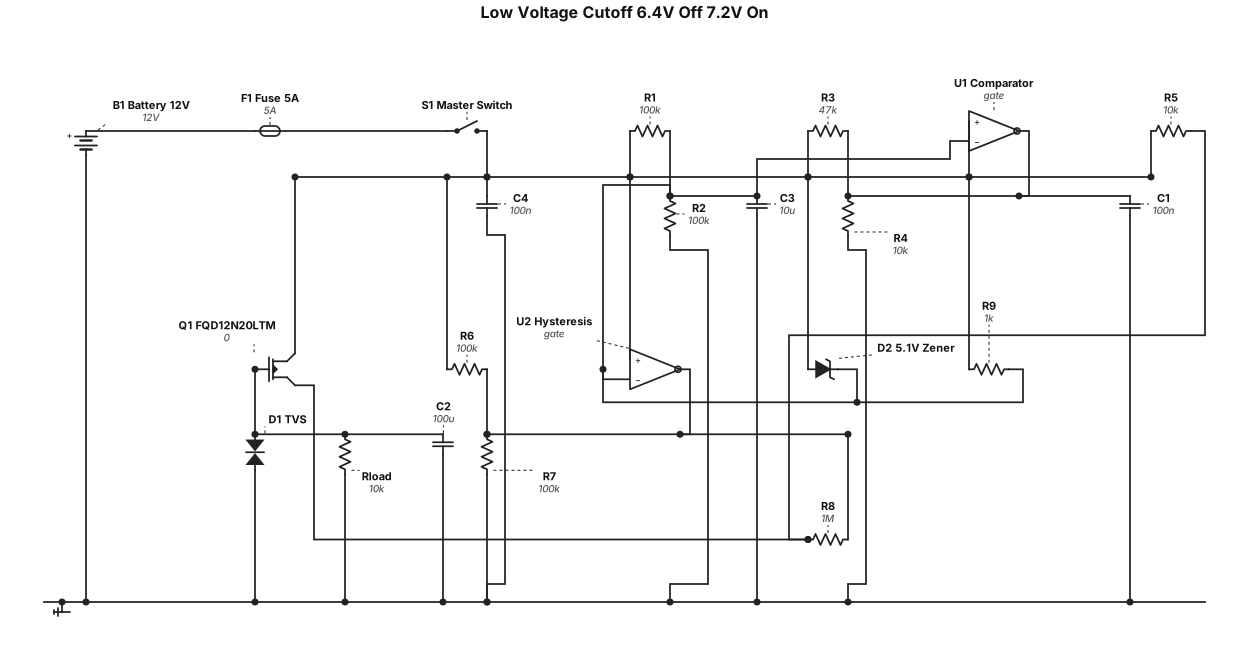
using a SMD parts like the FQD12N20LTM n-channel Mosfet show me a detailed circuit for a low voltage cut-off and on that will turn off the voltage at 6.4 and back on at 7.2 vdc
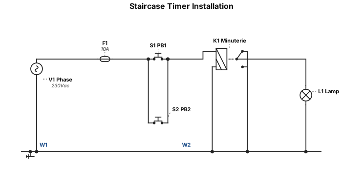
I am a beginner learning residential electrical installation (Électricité bâtiment). Teach me step by step in simple language. Explain electrical symbols, wiring diagrams, push buttons, staircase timers (minuterie d’escalier), and the difference between 3-wire and 4-wire connections. Use clear diagrams and explain every terminal. Do not guess connections; use the manufacturer's wiring diagram.

Create a complete, clear breadboard circuit diagram for an Emergency Shelter Occupancy Manager using these components: - 74LS192 BCD up/down counter - 74LS47 BCD-to-seven-segment decoder - 74HC08 AND gates - 74HC32 OR gates - Common-anode 7-segment display - Entry and exit pushbuttons - Green, yellow, and red LEDs - Buzzer - 7805 voltage regulator Show every IC pin number, all wire connections, resistor values, power and ground connections, and the breadboard layout. The counter must count from 0 to 9 for entry and decrease for exit. Prevent entry above 9 and exit below 0. Use real components and clearly label every connection. If any component is incompatible or the requested design needs additional components, explain the problem instead of guessing.
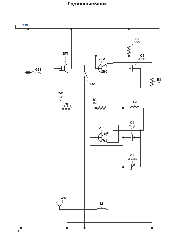
Сгенерируй принципиальную электрическую схему по следующему описанию. Используй стандартные УГО (условные графические обозначения) радиодеталей. Транзисторы NPN (полевые или биполярные, выводы: 1-Эмиттер, 2-База, 3-Коллектор). Компоненты: VT1, VT2 - биполярные NPN транзисторы. L1 - катушка связи (3-5 витков). L2 - контурная катушка (50-60 витков). C1 - конденсатор 150 пФ. C2 - подстроечный конденсатор 8-30 пФ (соединен параллельно C1). R1 - резистор 1 МОм. R2 - резистор 100 кОм. R3 - резистор 10 Ом. RV1 - потенциометр 10 кОм. C3 - конденсатор 0.22 мкФ. WA1 - антенна. BF1 - наушники. SA1 - выключатель. GB1 - источник питания (аккумулятор 3.7В). Соединения: 1. WA1 подключена к первому выводу L1. 2. Второй вывод L1 не подключен (висит в воздухе). 3. L2 и параллельная цепь (C1 || C2) образуют контур. Первый вывод контура подключен к База VT1. Второй вывод контура подключен к Эмиттер VT1. 4. R1 включен между Базой VT1 и Коллектором VT1. 5. Коллектор VT1 подключен к первому крайнему выводу RV1. 6. Второй крайний вывод RV1 подключен к общей минусовой шине. 7. Средний вывод (движок) RV1 подключен к первому выводу C3. 8. Второй вывод C3 подключен к Базе VT2. 9. R2 включен между Базой VT2 и плюсовой шиной питания. 10. Коллектор VT2 подключен к первому выводу BF1. 11. Второй вывод BF1 подключен к плюсовой шине питания. 12. Эмиттер VT2 подключен к первому выводу R3. 13. Второй вывод R3 подключен к общей минусовой шине. 14. Эмиттер VT1 подключен к общей минусовой шине. 15. Плюс GB1 подключен к плюсовой шине питания (к BF1 и R2). 16. Минус GB1 подключен к одному контакту SA1. 17. Второй контакт SA1 подключен к общей минусовой шине (к Эмиттеру VT1, R3 и RV1).
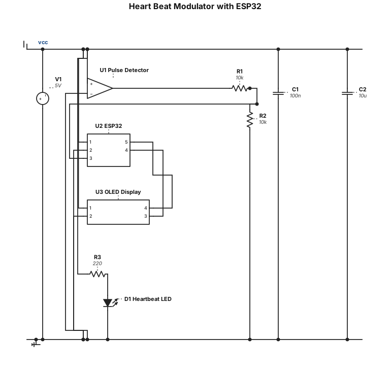
generate the mentioned heart beat modulator using an op amp and esp32 along with the other needed components to show the heart beat waves along with bpm on a led display and oxygen levels also we are using a ready pulse detector very simple circuit easy to understand and connect with proper naming and values
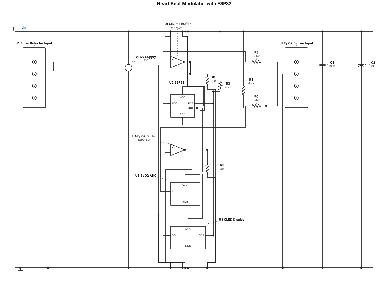
generate the mentioned heart beat modulator using an op amp and esp32 along with the other needed components to show the heart beat waves along with bpm on a led display and oxygen levels also we are using a ready pulse detector