
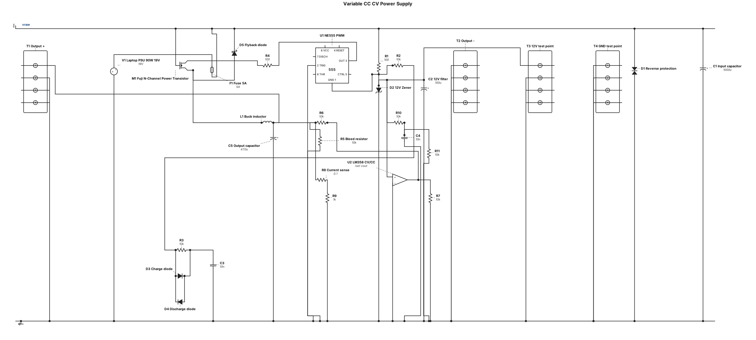
Please draw a circuit for a Variable CC CV Power Supply. The Power Supply runs from a Laptop universal Power Supply with 90 W 19 V. Please keep the components simple and explain every component. I have a NE 555 timer, an LM 358 Op Amp, and a Fuji N-Channel Power Transistor. The timer and the op-amp circuits should run with 12 Volts. Please mark the inputs and outputs, so that a person without advanced electronic skills can understand it.
ENGINEERING DRAWING ARCHIVE · REAL SPECS
Engineering Diagram Examples from Real Specifications
Browse eligible circuit, ladder, single-line, P&ID, breadboard, timing, and logic drawings with their original prompts.
Browse 548 real creationsCOMMUNITY OUTPUTS · EXACT PROMPTS
All visitor creations
Showing 289–312 of 548. No stock examples or system defaults. Choose a tool, study a real result, then reopen its prompt as your starting point.
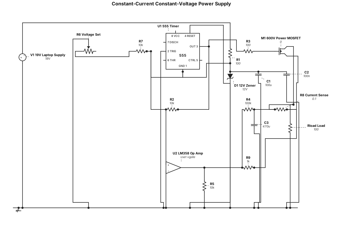
Can you create me simple circuit for a constant- current constant-voltage power supply with an input from a laptop universal 19 V power supply? Please explain in more detail the components. I have a 555 timer and an 358 Op Amp as well as a 600 V Power Mosfet wich ist pre-amplified for the needed Gate Voltage. The circuit for the 555 timer and the op amp should be 12 Volt.
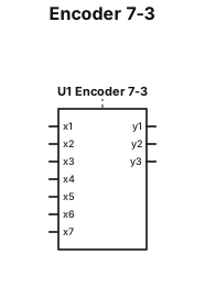
Draw a conditional graphic symbol (UGP) for a 7-to-3 encoder. It must be one rectangle. On the left side, draw 7 input lines labeled: x1, x2, x3, x4, x5, x6, x7. On the right side, draw 3 output lines labeled: y1, y2, y3. Inside the rectangle write: Encoder 7-3 Make it look like a standard digital logic block symbol.
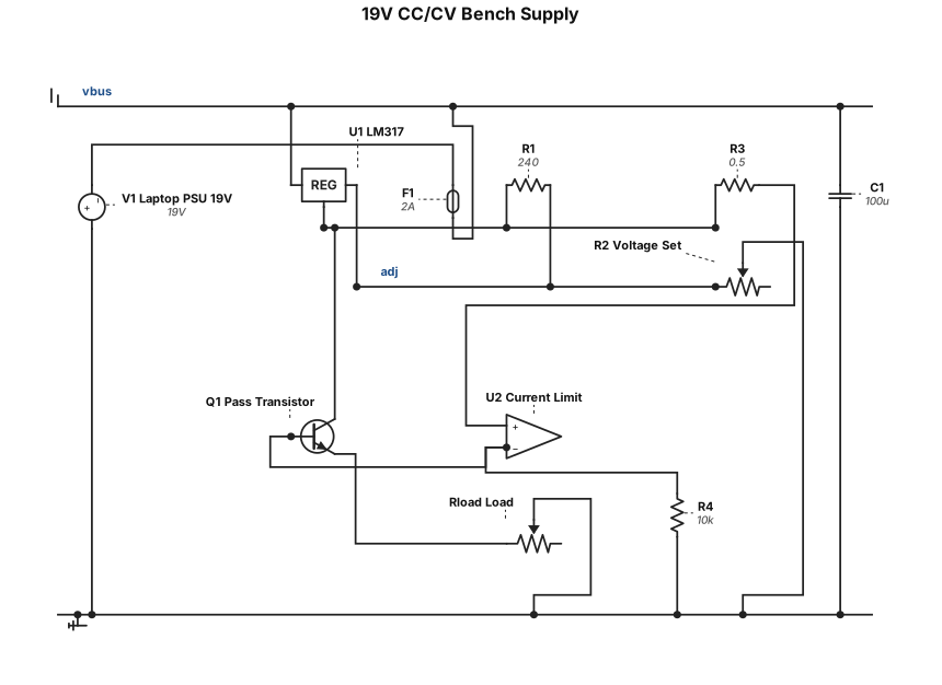
Can you create me simple circuit for a constant- current constant-voltage power supply with an input from a laptop universal 19 V power supply?
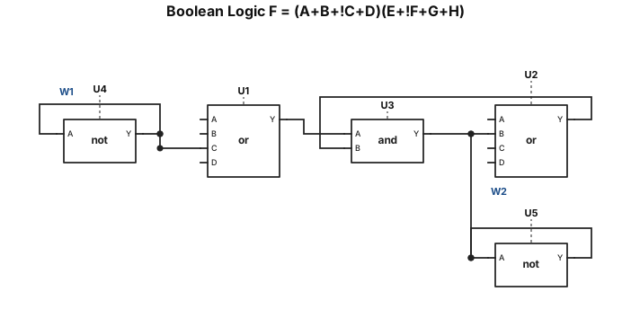
Draw a clean digital logic circuit for the Boolean function: F = (A OR B OR NOT C OR D) AND (E OR NOT F OR G OR H) Use NOT gates for C and F. Use two OR gates: - First OR gate: A, B, NOT C, D - Second OR gate: E, NOT F, G, H Then connect the outputs of both OR gates to one AND gate. The output of the AND gate is F. Label all inputs on the left and the output F on the right. Use a professional schematic style with clear connections.
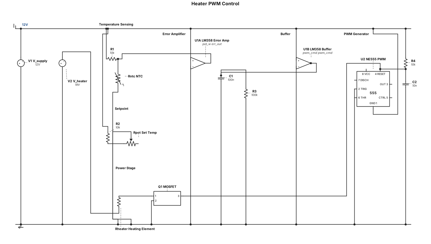
Hello. I want to create a Circuit to heat up a heating element (Resistor). The temperature of the resistor shall be measured via a thermistor and read in by an op amp. Maybe this should be a quad-op amp. The op amp should calculate the voltage for the next circuit, whitch ist driven by a NE 555 timer, providing a PWM-signal to control another circuit with a MOSFET as an amplifier for the heating element. I want to set a temperature for the heating element via a potentiometer. As an OP-amp i have for example one LM358. Can you make me a diagram with an explanation. Every circuit should later be packed in an individual box. Thank you. The circuits should work with 12 Volts. Only the mosfets Drain-Source Voltage is 19 Volts.
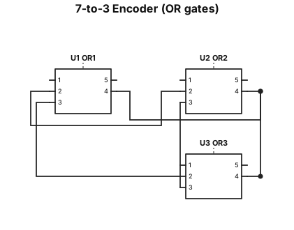
Draw a clean digital logic circuit for a 7-to-3 encoder. Inputs: x1, x2, x3, x4, x5, x6, x7. Outputs: y1, y2, y3. Use OR gates only. The logic functions are: y1 = x1 OR x3 OR x5 OR x7 y2 = x2 OR x3 OR x6 OR x7 y3 = x4 OR x5 OR x6 OR x7 Label all inputs on the left and all outputs on the right. Make the connections clear and use a professional schematic style.
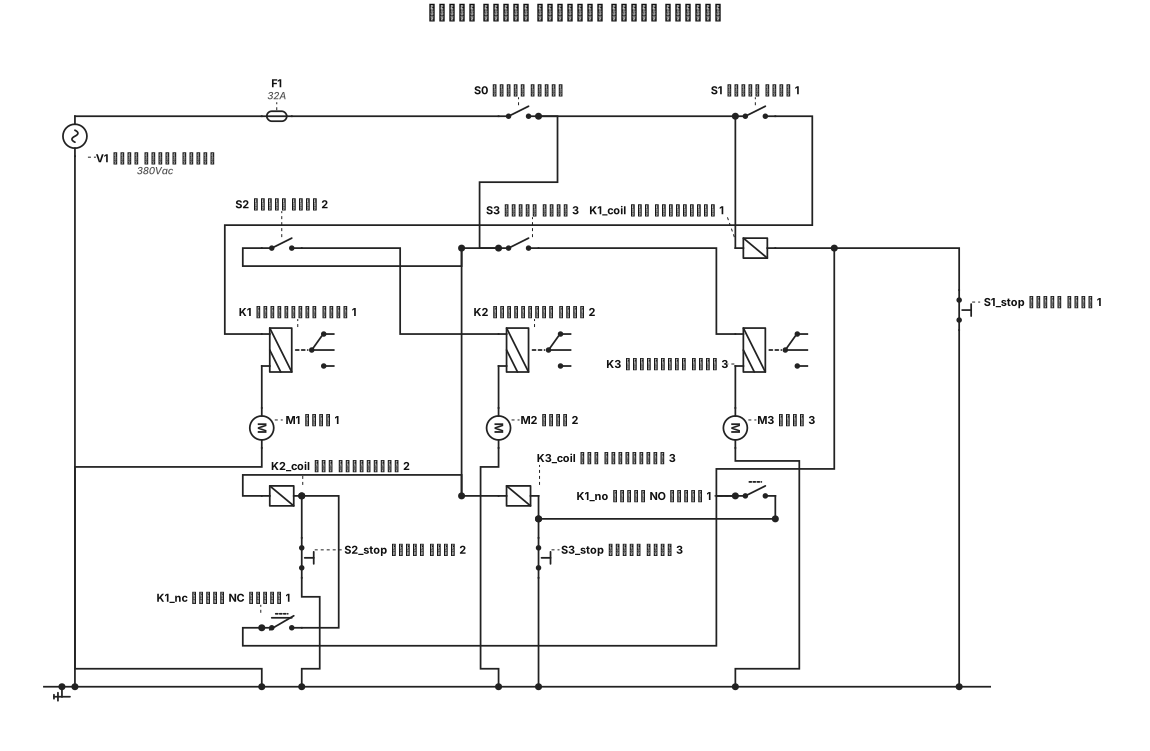
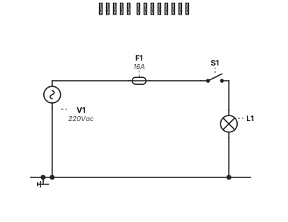
دائرة القوى والتحكم لثلاث محركات الأول يعمل في أي وقت تشاء والثاني لا يعمل الا في حالة وقوف الأول والثالث لا يعمل الا في حالة دوران الأول لكل محرك مفتاح تشغيل ومفتاح إيقاف واحد رئيسي
عايز دا
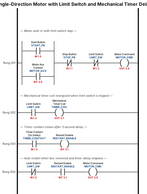
SINGLE-DIRECTION motor circuit which will stop when a box gets to the end with a limit switch, and then RESTARTS after on its own when the box is removed AFTER A THREE SECOND DELAY. using mechanical timer not function block. it also need to have a start stop button and not use a timer block but a mechanical timer not for PLC's
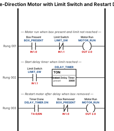
SINGLE-DIRECTION motor circuit which will stop when a box gets to the end with a limit switch, and then RESTARTS after on its own when the box is removed AFTER A THREE SECOND DELAY. using mechanical timer not function block.
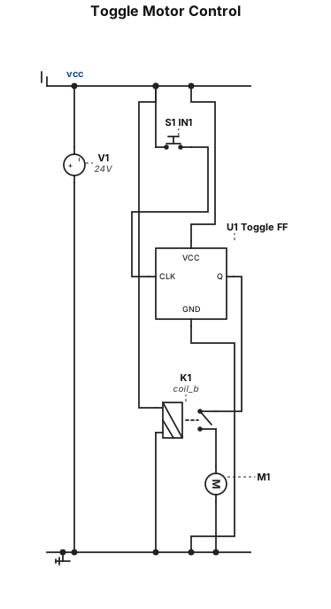
Would you able to create this logic circuit? We have a single user input IN1 that will start a motor M1, this input is momentary, but the motor should continue to run until the input is pressed again.
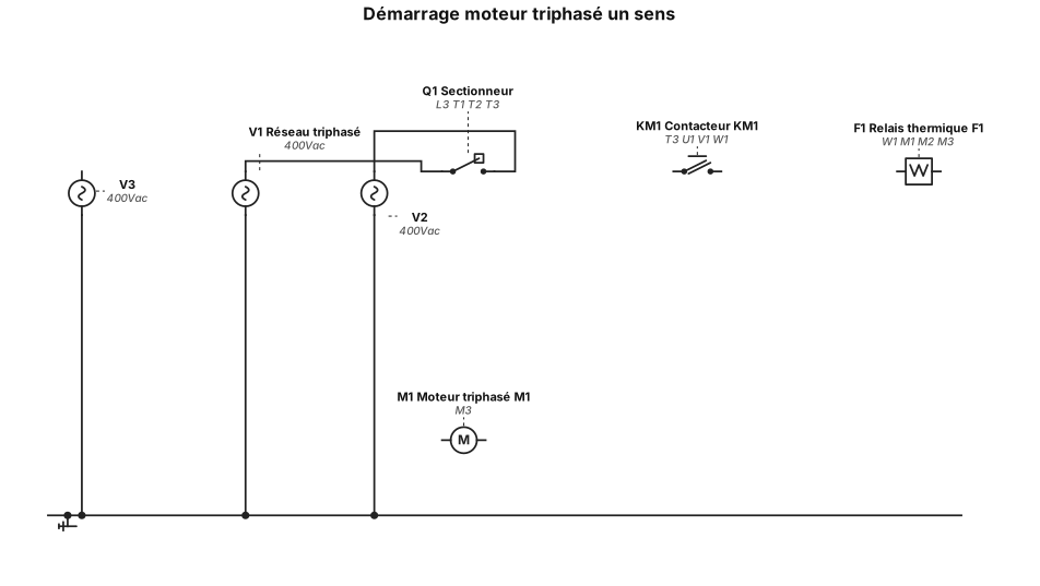
realise un motage moteur triphaser avec le sectionneur le contacteur et le relais thermique a un sens de marche
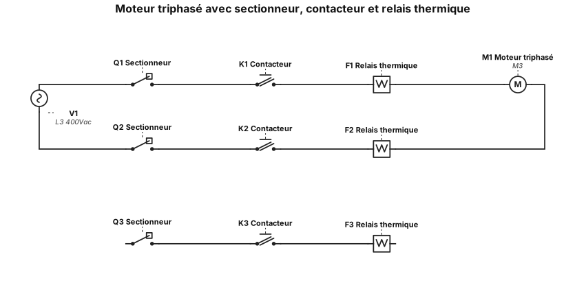
realise un motage moteur triphaser avec le sectionneur le contacteur et le relais thermique
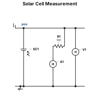
A solar cell's negative is conencted to ammeters positive and the ammeters negative is connected to a resistor and the resistors other terminal is connected to solar cell's positive and the resistor has a voltage in parallel to it
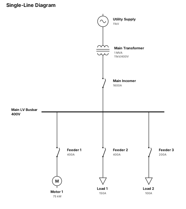
Create a clear single-line diagram with concise labels and the standard notation for this subject.
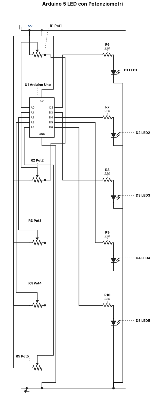
Genera lo stesso schema di prima ma adattandolo ad arduino, avendo 5 led indipendenti controllati da un potenziometro ciascuno
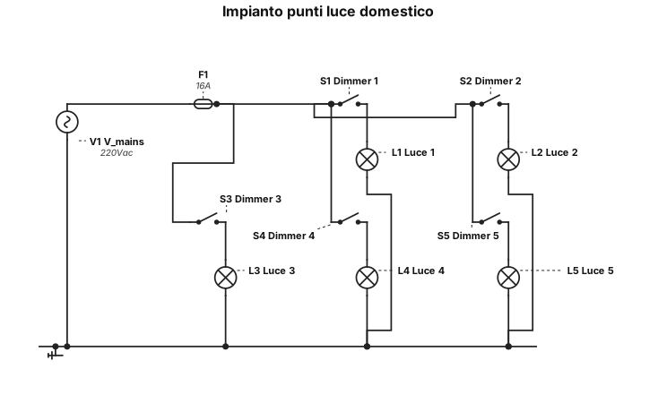
Genera un impianto elettrico domestico per i soli punti luce, le luci devono essere 5 e saranno indipendenti tra loro, ognuna dotata di un dimmer
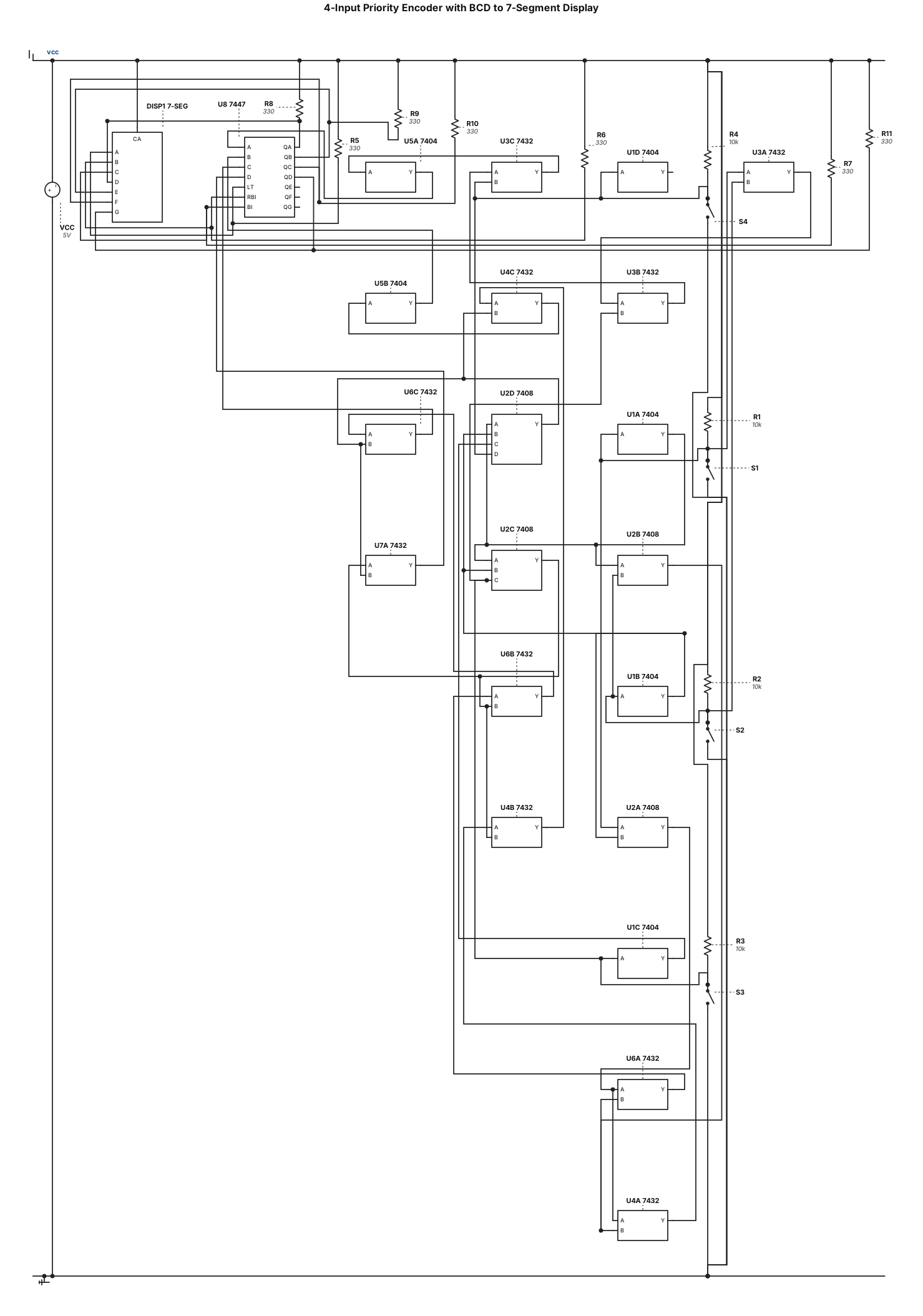
Design a complete digital logic circuit for a 4-input priority encoder connected to a BCD-to-7-segment display decoder. INPUTS: Use four independent digital switches named S1, S2, S3 and S4. Logic 1 means ON, and logic 0 means OFF. PRIORITY RULES: * If S1 = 1, display digit 1, regardless of S2, S3 and S4. * If S1 = 0 and S2 = 1, display digit 2, regardless of S3 and S4. * If S1 = 0, S2 = 0 and S3 = 1, display digit 3, regardless of S4. * If S1 = 0, S2 = 0, S3 = 0 and S4 = 1, display digit 4. * If all four switches are 0, display digit 0. IGNORE all other switches in the circuit. OUTPUT: Connect the logic circuit to a BCD-to-7-segment decoder and a common-anode 7-segment display. Display the correct decimal digit for every possible input combination. IMPLEMENTATION: Use basic logic gates and, where appropriate, 7404 NOT gates, 7408 AND gates and 7432 OR gates. Use a compatible BCD-to-7-segment decoder such as the 7447/74LS47. Show: 1. A complete, clearly labelled circuit diagram. 2. All logic gates and their connections. 3. The Boolean equations for all four BCD output bits. 4. The complete truth table. 5. Correct IC pin connections and power connections. 6. A circuit that can be tested in a digital logic simulator. Do not generate only a conceptual block diagram. Generate the actual gate-level circuit.
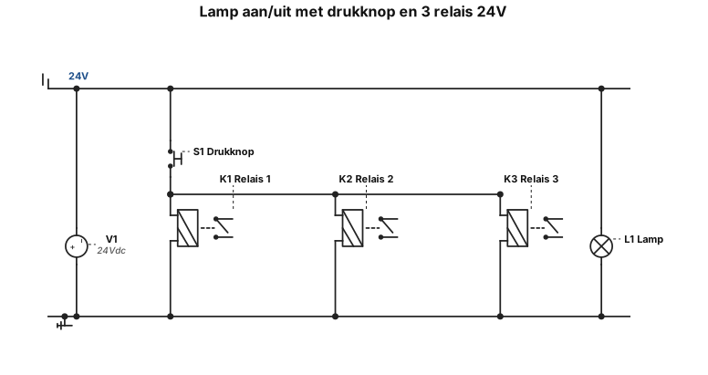
hoe een lamp aan en uit zeten met een drukknop en 3 reles bestuuren 24V
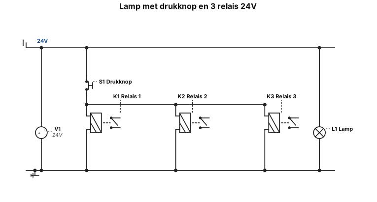
hoe een lamp met een drukknop en 3 reles bestuuren 24V
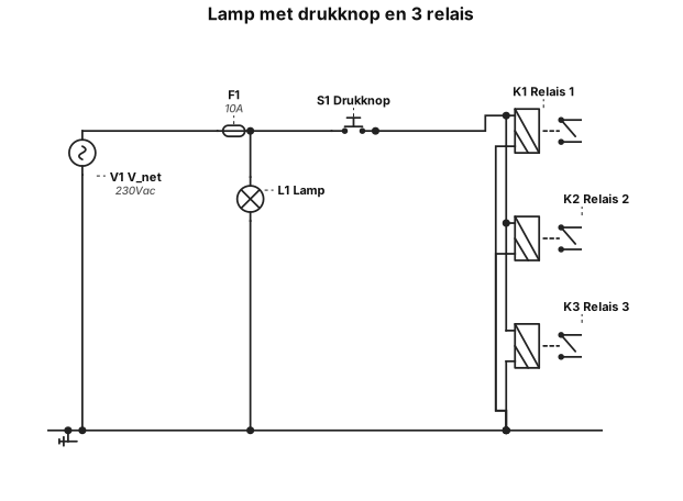
hoe een lamp met een drukknop en 3 reles bestuuren
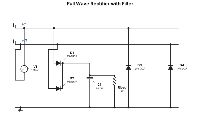
FULL WAVE RECTIFIER CIRCUIT WITH FILTER
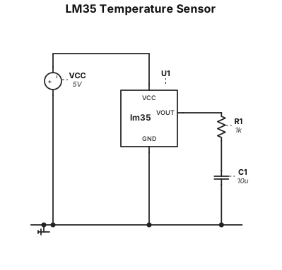
Use an LM35 temperature sensor. Connect pin 1 (VCC) to +5 V. Connect pin 3 (GND) to common ground. Connect pin 2 (VOUT) to a wire labelled VS. Connect VS to a 1 kΩ resistor in series. Connect the other end of the resistor to a node labelled VOUT. Connect a 10 µF capacitor between VOUT and common ground.