
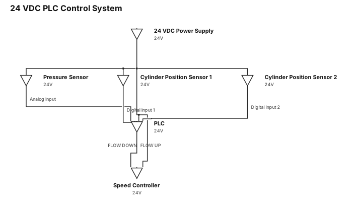
Show a 24 VDC power supply feeding the PLC, pressure sensor, two cylinder position sensors, and speed controller. Show the pressure sensor’s analog output connected to a PLC analog input, and the two position sensors connected to separate digital inputs. Show two separate PLC digital outputs connected to the speed controller’s “FLOW UP” and “FLOW DOWN” inputs.
ENGINEERING DRAWING ARCHIVE · REAL SPECS
Engineering Diagram Examples from Real Specifications
Browse eligible circuit, ladder, single-line, P&ID, breadboard, timing, and logic drawings with their original prompts.
Browse 549 real creationsCOMMUNITY OUTPUTS · EXACT PROMPTS
All visitor creations
Showing 361–384 of 549. No stock examples or system defaults. Choose a tool, study a real result, then reopen its prompt as your starting point.
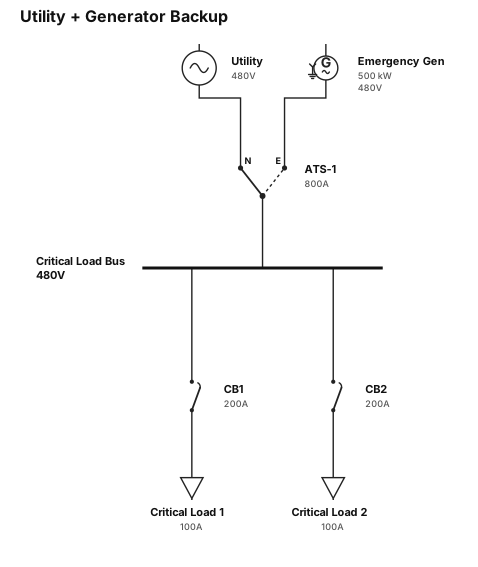
A 480 V utility and 500 kW emergency generator feeding an 800 A automatic transfer switch, then a critical-load bus with two 200 A breakers and two 100 A loads.
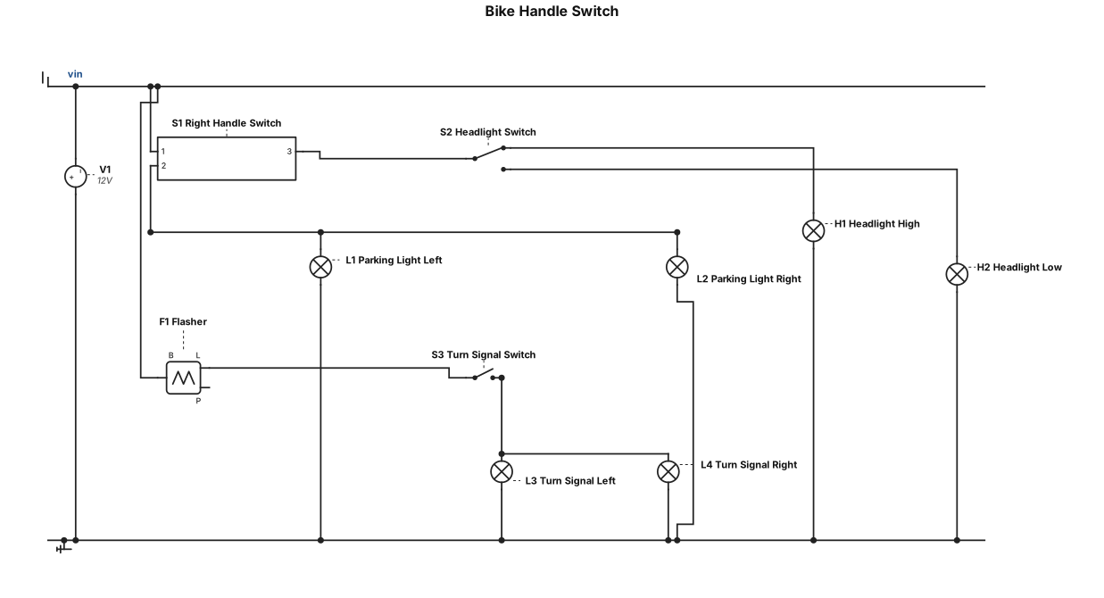
Easy bike handle switch drawing, there will be a two-pole switch on the right side, one will have 12 volts in, from the other two wires will come out from the same pole, 12 volts. From there, one will go to the parking lights on both sides. A wire will come from the same pole and connect to the middle of the handle switch. This will come out from both sides of the three-pole switch and will be the high and low output of the headlight. A 12-volt line will come directly into a flasher and from there it will come to the
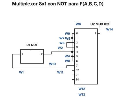
Dibuja un esquema eléctrico digital claro, en blanco y negro, para un ejercicio de Fundamentos de Computadores. Debe implementar un circuito combinacional usando exclusivamente un multiplexor 8×1 y una puerta NOT. La función es F(A,B,C,D)=1 cuando el número binario ABCD es múltiplo de 2, 5 o 7, incluyendo el cero. Conecta las selecciones del multiplexor como S2=A, S1=B y S0=C. Conecta las entradas de datos así: I0=D', I1=D', I2=1, I3=1, I4=D', I5=D', I6=D' e I7=D. Dibuja una puerta NOT con entrada D y salida D'. Muestra todos los cables, las ramificaciones, las ocho entradas de datos, las tres entradas de selección y la salida F. Etiqueta todos los elementos. No omitas conexiones ni añadas componentes. Comprueba la lógica antes de generar el dibujo.
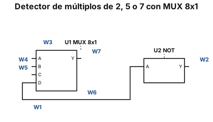
Se desea implementar un circuito lógico combinacional que produzca una salida uno si los cuatro bits de entrada ABCD interpretados en binario natural son múltiplo exacto de alguno de los números 2, 5 ó 7, y una salida cero en caso contrario. El cero se considerará múltiplo exacto de cualquier número, así que la salida deseada para la entrada ABCD=0000 será en todo caso un uno. Para diseñar dicho circuito se dispone únicamente de UN MUX 8x1 Y, SI ES NECESARIO, UN INVERSOR (PUERTA NOT). Las variables que se emplearán para alimentar las entradas de control del multiplexor deberán ser A, B y C. Dibujar en un papel el circuito resultante, donde se aprecien claramente los valores y/o variables con que se alimentan todas las entradas (datos y control) del mismo.
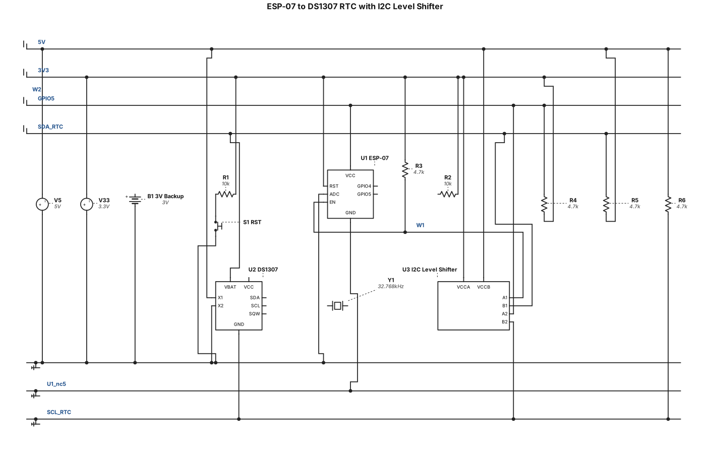
Create an accurate electrical schematic connecting an ESP-07 ESP8266MOD 16-pin module to a DS1307 RTC DIP-8 IC. ESP-07 connections: - Pin 1 RST: connect a normally-open pushbutton from RST to GND, plus a separate 10kΩ pull-up resistor from RST to 3.3V. - Pin 2 ADC: NC, no connection. - Pin 3 EN/CH_PD: separate 10kΩ pull-up resistor to 3.3V. - Pin 8 VCC: regulated 3.3V. - Pin 9 GND: common ground. - Pin 13 GPIO4: I2C SDA. - Pin 14 GPIO5: I2C SCL. DS1307 DIP-8 pinout, top view with notch at the top: 1 X1, 2 X2, 3 VBAT, 4 GND, 5 SDA, 6 SCL, 7 SQW/OUT, 8 VCC. DS1307 connections: - Pins 1 and 2: connect a 32.768kHz crystal between X1 and X2. - Pin 3 VBAT: positive of a 3V backup battery; battery negative to common ground. - Pin 4 GND: common ground. - Pin 5 SDA: connect to ESP GPIO4 through a bidirectional I2C level shifter. - Pin 6 SCL: connect to ESP GPIO5 through the same level shifter. - Pin 7 SQW/OUT: NC. - Pin 8 VCC: regulated 5V. Include a correctly wired bidirectional I2C level shifter, with 3.3V pull-ups on the ESP side and 5V pull-ups on the DS1307 side. Never apply 5V to any ESP8266 GPIO. Draw a clean black-and-white engineering schematic with exact pin numbers, straight wires, visible junction dots, separate 3.3V and 5V rails, and common ground. Do not invent or swap pin connections. If a connection cannot be drawn reliably, label it for verification instead of guessing.
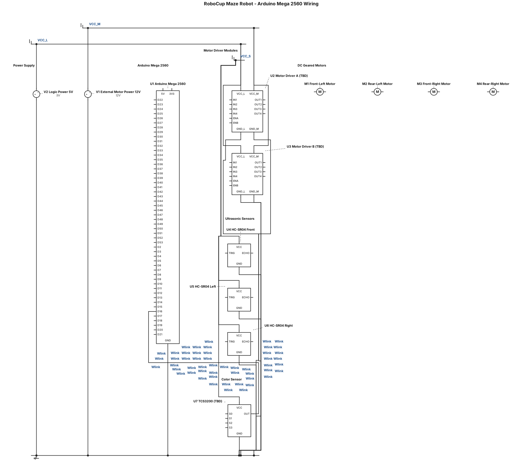
Create a detailed, neat, landscape-format electrical wiring diagram for a RoboCup maze-solving robot using an Arduino Mega 2560. COMPONENTS: 1. One Arduino Mega 2560. 2. Two dual-channel DC motor driver modules, each controlling two DC motors. 3. Four DC geared motors: front-left, rear-left, front-right, and rear-right. 4. Three HC-SR04 ultrasonic distance sensors: front, left, and right. 5. One TCS3200/TCS230 color sensor. DIAGRAM REQUIREMENTS: - Draw the actual Arduino Mega 2560 with its labeled digital pins, PWM pins, 5V, 3.3V, and GND. - Draw both motor driver modules with their control inputs, enable/PWM pins, motor outputs, logic power, motor power, and ground terminals. - Show all four motors connected to the correct motor driver outputs. - Draw each ultrasonic sensor with VCC, GND, TRIG, and ECHO pins. - Draw the TCS3200 color sensor with VCC, GND, S0, S1, S2, S3, and OUT pins. - Draw every wire separately and label BOTH ends of every connection with the exact pin names. - Use different colors for power, ground, motor control, and sensor signal wires. - Include a clear pin-to-pin connection table. - Show a suitable external motor power supply and common ground. - Do not power the motors directly from the Arduino 5V pin. - Avoid pin conflicts and account for PWM requirements. - Keep the diagram readable and suitable for printing as a PDF. IMPORTANT ACCURACY RULES: - Do not invent component models, pin connections, or electrical specifications. - The motor driver model has not yet been confirmed. Mark driver-specific connections as TBD until the exact model is known. - Use the TCS3200/TCS230 only as a provisional sensor choice; mark it TBD until confirmed. - Clearly identify any missing information. - Do not claim that the diagram has been electrically simulated or verified. OUTPUT: Generate a clear, professional, labeled wiring diagram and a pin-to-pin connection table for the Arduino Mega 2560 robot.
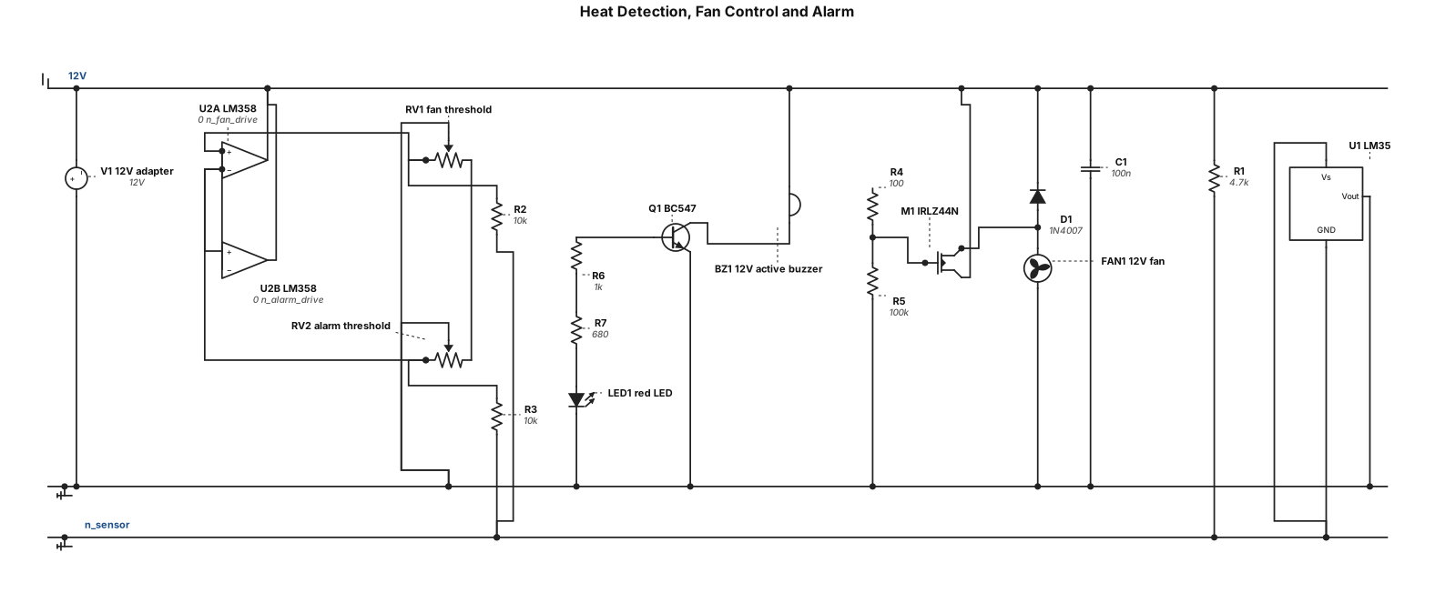
Design a detailed, beginner-friendly schematic for a low-voltage analog heat detection, automatic cooling fan, and high-temperature alarm project for an EEE college demonstration. Components available: LM35 temperature sensor (or TMP36 if the LM35 is unavailable), LM358P DIP-8 dual op-amp, two 10 kΩ PT10-2 potentiometers, IRLZ44N logic-level N-channel MOSFET, BC547 NPN transistor, 12 V DC fan, 12 V active buzzer, red LED, 1N4007 diode, resistors of 100 Ω, 1 kΩ, 4.7 kΩ, 100 kΩ and 680 kΩ, 100 nF capacitor, and a regulated 12 V adapter. Requirements: 1. Draw every component with reference designators and values. 2. Show exact pin numbers for the LM358, sensor, MOSFET, and BC547. 3. Label all power rails and grounds. 4. Include the fan flyback diode, LED current-limiting resistor, and safe buzzer driver. 5. Provide separate adjustable fan-on and alarm thresholds. 6. Check sensor voltage, comparator input range, MOSFET gate drive, resistor values, and output current limits. 7. Do not assume the design is correct merely because a schematic was generated. Identify uncertain connections and simulate or verify them before recommending construction. 8. Produce an editable schematic and a complete connection-by-connection wiring table. 9. If using TMP36, recalculate the threshold circuit for its voltage offset and specify its correct supply and pinout. Use low-voltage DC only; this is a demonstration project, not a certified fire alarm.
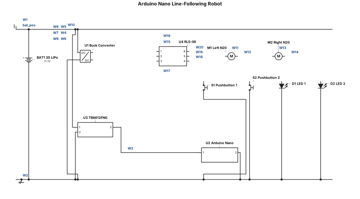
Draw a simple wiring schematic for an Arduino Nano line-following robot. Components: Arduino Nano, TB6612FNG motor driver, RLS-06 line sensor, two N20 motors, two pushbuttons, two LEDs, a DC-DC buck converter, and a 3S LiPo battery. Connections: Arduino D2 to PWMB Arduino D3 to BIN2 Arduino D4 to BIN1 Arduino D5 to STBY Arduino D6 to AIN1 Arduino D7 to AIN2 Arduino D8 to PWMA Arduino D9 to pushbutton 1 Arduino D10 to pushbutton 2 Arduino D11 to LED 1 Arduino D12 to LED 2 Arduino A0-A5 to the RLS-06 sensor Motor driver AO1 and AO2 to the left motor Motor driver BO1 and BO2 to the right motor Battery positive to motor driver VM and buck converter input positive Battery negative to motor driver GND and buck converter input negative Motor driver VCC to 5V Buck converter output positive to Arduino VIN Buck converter output negative to Arduino GND Use clear labels and straight connection lines. White background. Do not add connections that are not listed.
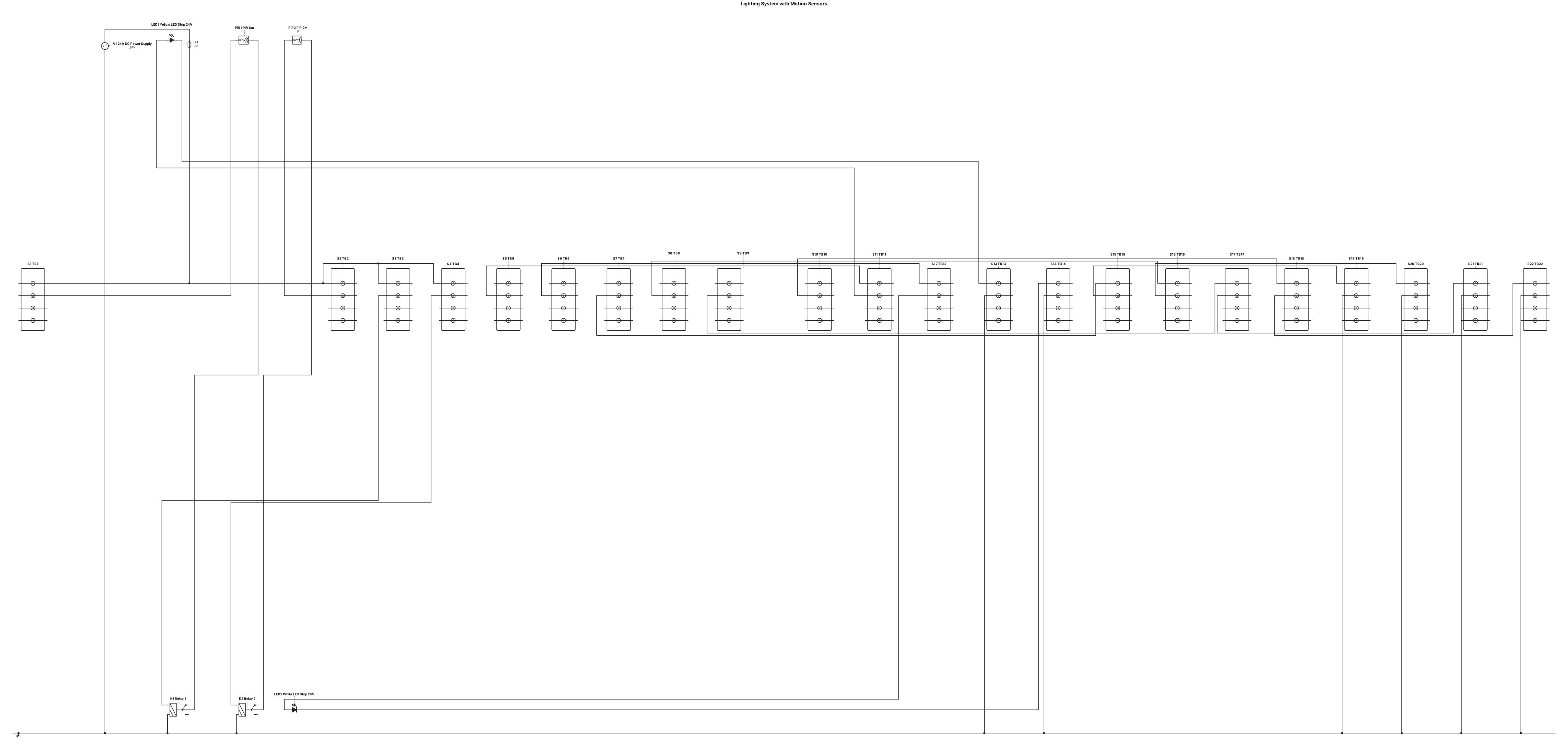
Design a wiring diagram for a lighting system. The components used are: 1× white LED strip, 24 V 1× yellow LED strip, 24 V 1× 24 V DC power supply 2× 24 V relays (COM, NO, NC) 1× PIR motion sensor with an 8 m detection range and a timer adjustable up to 7 minutes 1× motion sensor with a 2 m detection range and a timer adjustable up to 7 minutes You may use any number of terminal blocks, and an unlimited number of wires are available. The wiring system must operate as follows: The yellow LED strip must be activated when the motion sensor with an 8 m detection range is triggered. The white LED strip must be activated when the motion sensor with a 2 m detection range is triggered. Both motion sensors are installed in the same location. Both LED strips are installed in the same location. The two LED strips must never be illuminated simultaneously.
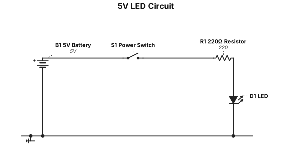
Create a simple 5V LED circuit with a 220-ohm resistor, switch, battery, and clear component labels.
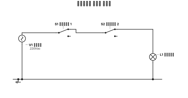
رسم دائره وسط سلم
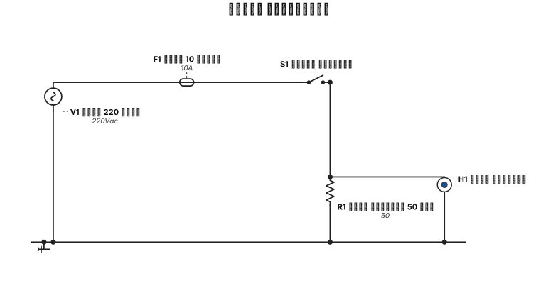
رسم دائره الدفياتير
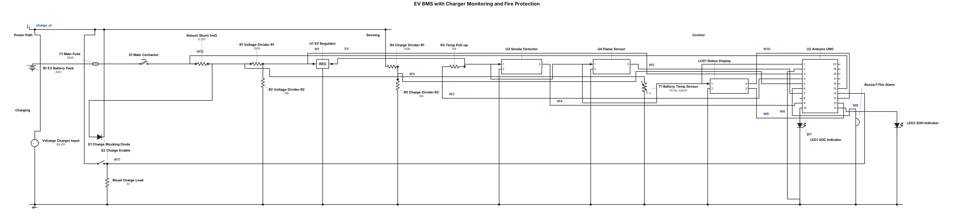
EV BMS with Charger Monitoring and Fire Protection along with SOC,SOH using Arduino UNO.
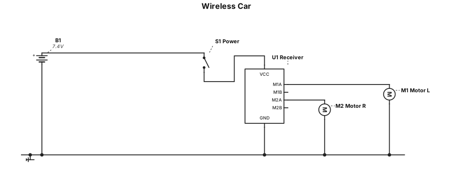
wire less car
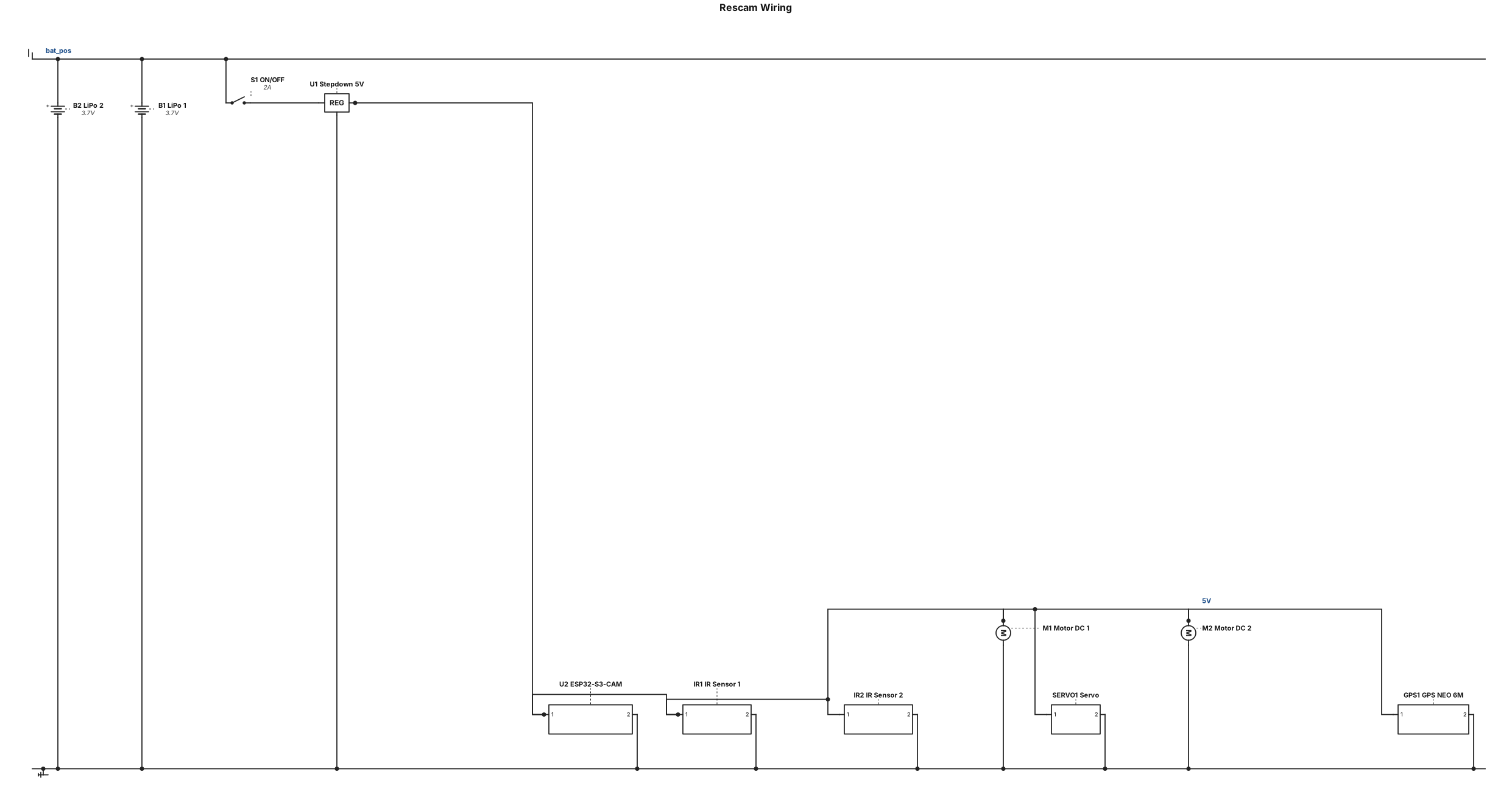
buatkan wiring untuk project ku yang bernama rescam komponennya ada: ESP32-S3-CAM, IR SENSOR 2x, Baterai LiPo 2x, servo, morot DC 2x, GPS NEO 6M, ON/OFF SWITCH, stepdown 5v
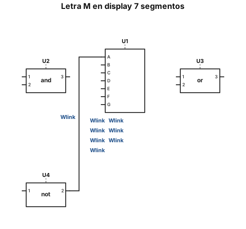
necesito que con la compuestas logicas and,not,or junto un display de 7 segmentos hagan la letra m con a,f,g,e,d
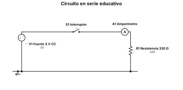
Crea un esquema eléctrico educativo, muy sencillo y claramente etiquetado, de un circuito en serie con una fuente de corriente continua de 5 V, un interruptor y una resistencia de 330 Ω. Muestra todos los cables, los terminales positivo y negativo, y un amperímetro conectado en serie. Fondo blanco, líneas claras y etiquetas grandes en español. No agregues componentes adicionales.
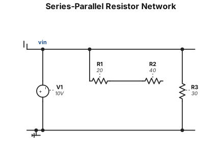
a 10V source drives a 20Ω and 40Ω resistor in series, parallel with a 30Ω resistor. find rt
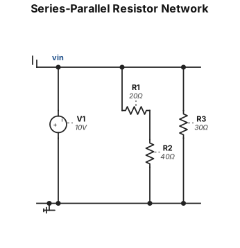
a 10V source drives a 20Ω and 40Ω resistor in series, parallel with a 30Ω resistor
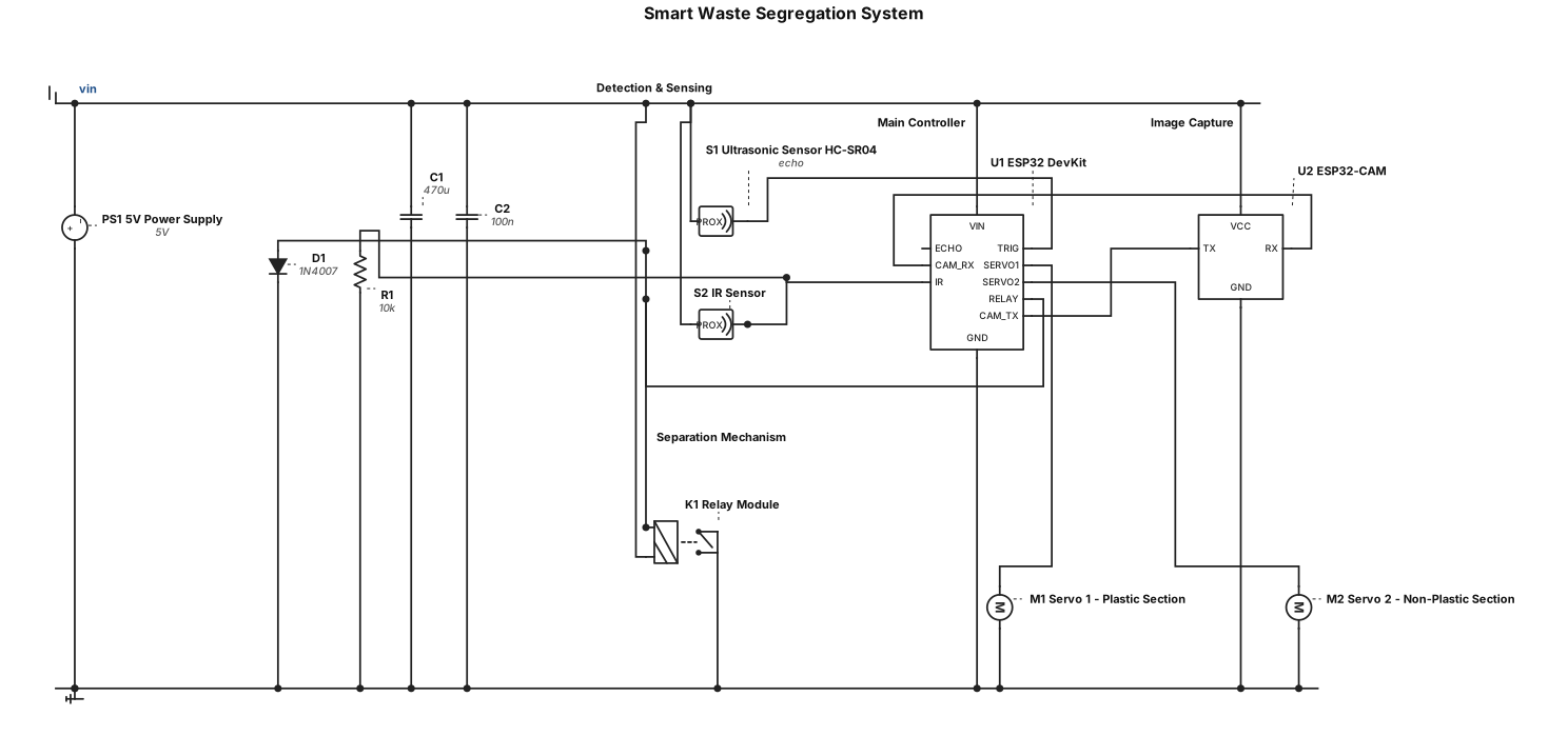
Hi, I am working on a Smart Waste Segregation Project. My Project Idea The main aim of my project is to automatically identify plastic and non-plastic waste and separate them into different sections. Components I Have - ESP32 DevKit – main controller - ESP32-CAM – captures the image of the waste - Ultrasonic sensor – detects the object/distance - IR sensor – detects the presence of an object - 2 Servo motors – moves the waste to the correct section - Relay module - Breadboard - Jumper wires - 5V power supply How I Want It to Work 1. A waste item is placed into the system. 2. The ultrasonic/IR sensor detects the object. 3. The ESP32-CAM captures its image. 4. The system identifies whether it is plastic or non-plastic. 5. The ESP32 receives the result. 6. Based on the result, the servo motor moves the waste to the correct section. 7. Then the system is ready for the next item. Important Requirement If multiple plastic and non-plastic items are put together, I want the system to process them one by one, so that the camera can identify each item properly. I need help with the complete circuit connection, ESP32 + ESP32-CAM communication, image classification method, coding, and the mechanical separation mechanism. My final goal is to make a proper working model where: Waste detected → Image captured → Plastic/Non-Plastic identified → Automatically separated.
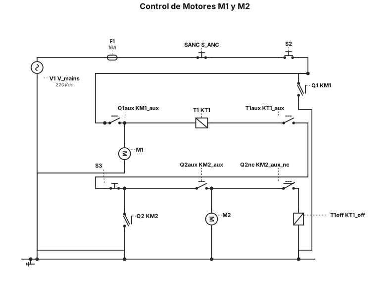
S2 NO produce la mancha de M1. lo segundos después arranca M2. SANC solo detiene a M1 S3 NC solo detiene a M2 Proteger con guandamotores PISTAS → redimentar a Q2 pmotor 2 1 Cando arange M2 descondó al temporizador → usar contactos aukliares.
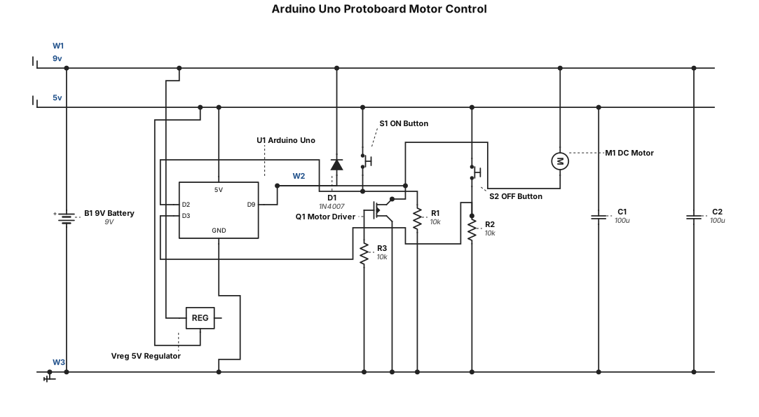
generate it in a protoboard for arduino one and a protoboard basic, give me a circuit with 2 push buttoms that control a motor, one of them for turning it on, and other for turning off, and a 9v baterry powering que motor
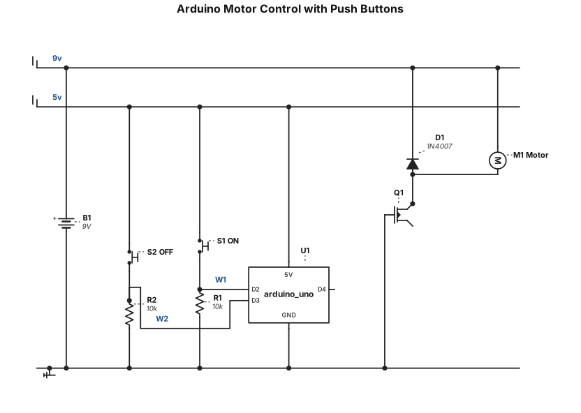
for arduino one and a protoboard basic, give me a circuit with 2 push buttoms that control a motor, one of them for turning it on, and other for turning off, and a 9v baterry powering que motor