
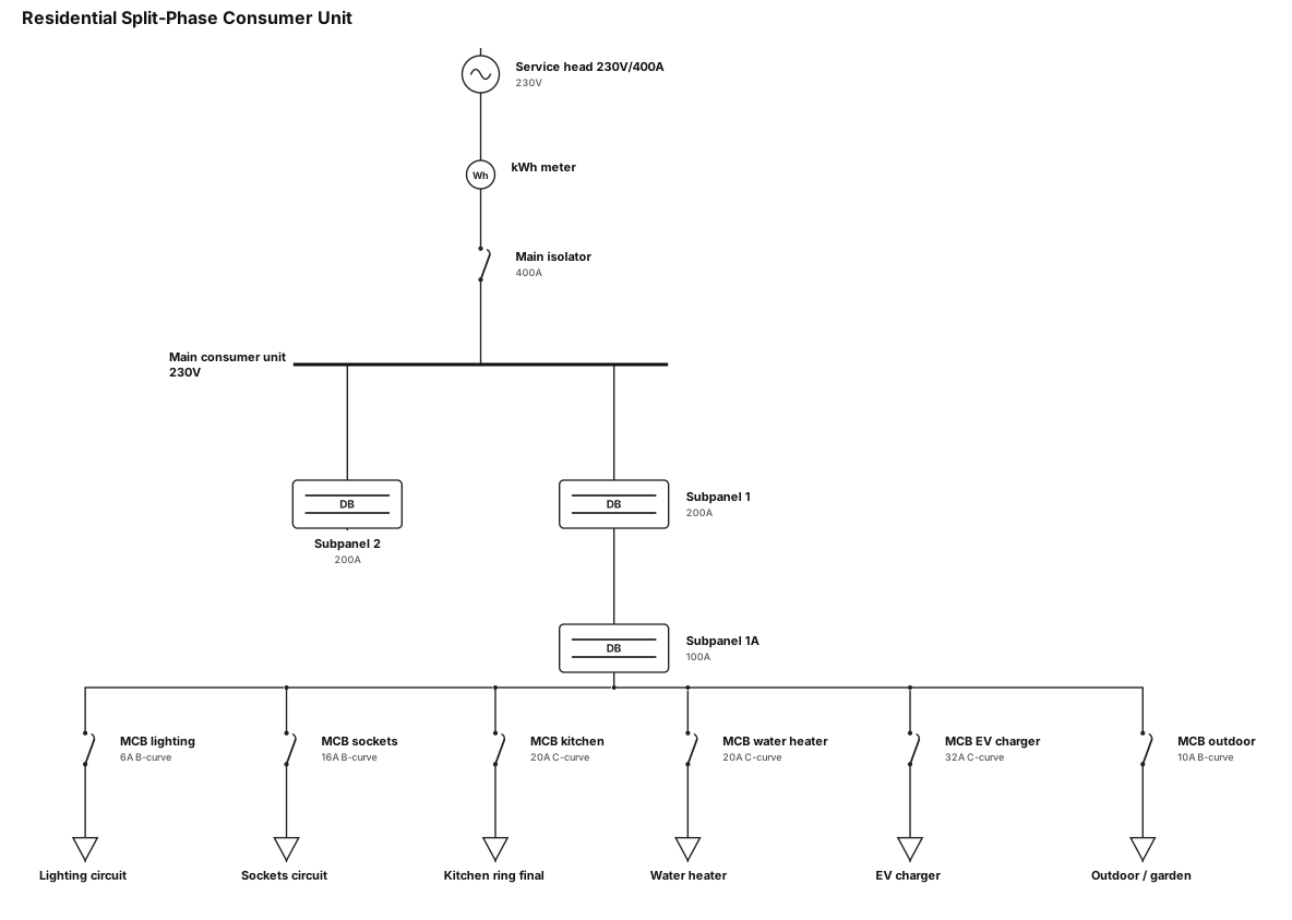
A 230 V residential split phase consumer unit with a meter, 400 A main isolator, two 200 A subpanels, subpanel 1 has a subpanel and separate breakers for lighting, sockets, kitchen, water heater, EV charger, and outdoor circuit.
ENGINEERING DRAWING ARCHIVE · REAL SPECS
Engineering Diagram Examples from Real Specifications
Browse eligible circuit, ladder, single-line, P&ID, breadboard, timing, and logic drawings with their original prompts.
Browse 549 real creationsCOMMUNITY OUTPUTS · EXACT PROMPTS
All visitor creations
Showing 385–408 of 549. No stock examples or system defaults. Choose a tool, study a real result, then reopen its prompt as your starting point.
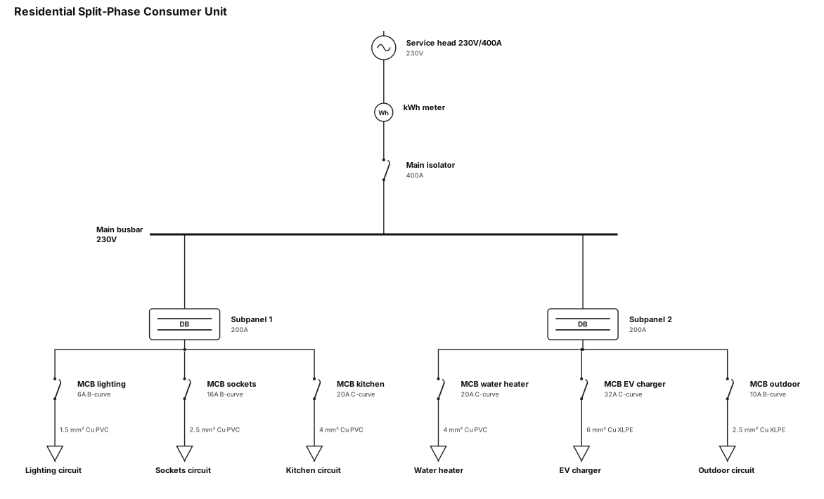
A 230 V residential split phase consumer unit with a meter, 400 A main isolator, two 200 A subpanels, and separate breakers for lighting, sockets, kitchen, water heater, EV charger, and outdoor circuit.
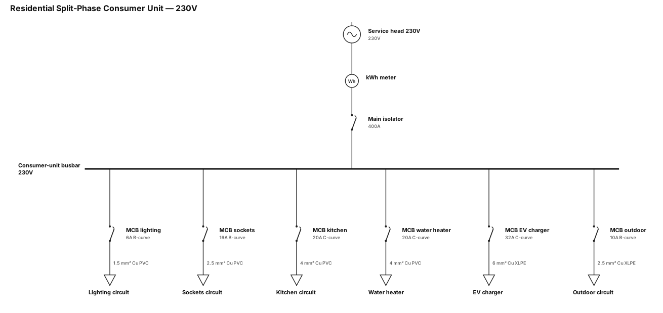
A 230 V residential split phase consumer unit with a meter, 400 A main isolator, busbar, and separate breakers for lighting, sockets, kitchen, water heater, EV charger, and outdoor circuit.
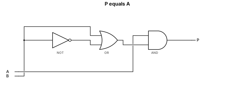
2.1 P equals A left parenthesis B plus top enclose B right parenthesis left parenthesis B plus top enclose B right parenthesis equals 1 P equals A left parenthesis 1 right parenthesis t h e r e f o r e comma space P equals A draw a logic circuit and labe: input, output P and required logic gate
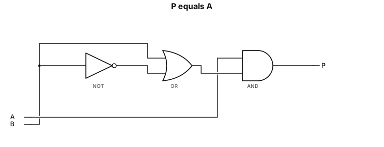
2.1 P equals A left parenthesis B plus top enclose B right parenthesis left parenthesis B plus top enclose B right parenthesis equals 1 P equals A left parenthesis 1 right parenthesis t h e r e f o r e comma space P equals A draw a logic circuit
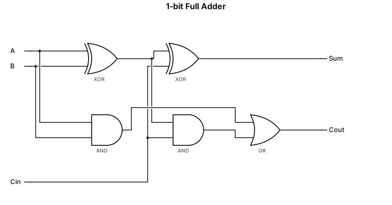
A one-bit full adder with inputs A, B, and carry-in, XOR gates for Sum, AND gates for partial carries, and an OR gate for carry-out.
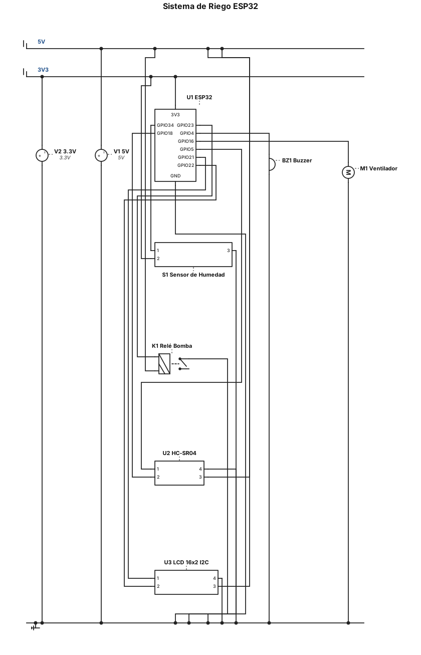
### 1. Sensores y Actuadores Principales - **Sensor de Humedad del Suelo (Analógico):** - Pin de señal (AO) $\rightarrow$ **Pin 34** de la ESP32 - VCC $\rightarrow$ 3.3V o 5V (según tu módulo) - GND $\rightarrow$ GND - **Módulo de Relé (Bomba de Agua):** - Pin de control (IN) $\rightarrow$ **Pin 23** - VCC $\rightarrow$ 5V - GND $\rightarrow$ GND - **Buzzer (Alarma):** - Pin positivo (+) $\rightarrow$ **Pin 4** - Pin negativo (-) $\rightarrow$ GND - **Ventilador (vía Driver L293D / Transistor):** - Pin de control de velocidad/activación (IN1) $\rightarrow$ **Pin 16** ### 2. Sensor Ultrasónico (HC-SR04 - Nivel de Agua) - **Trig:** Conectado al **Pin 5** - **Echo:** Conectado al **Pin 18** *(Nota: El pin Echo trabaja a 5V, idealmente usa un divisor de tensión con resistencias si quieres proteger la ESP32, aunque muchos módulos funcionan directo)* - **VCC:** 5V - **GND:** GND ### 3. Pantalla LCD 16x2 con Adaptador I2C - **SDA:** Conectado al **Pin 21** de la ESP32 - **SCL:** Conectado al **Pin 22** de la ESP32 - **VCC:** 5V - **GND:** GND .
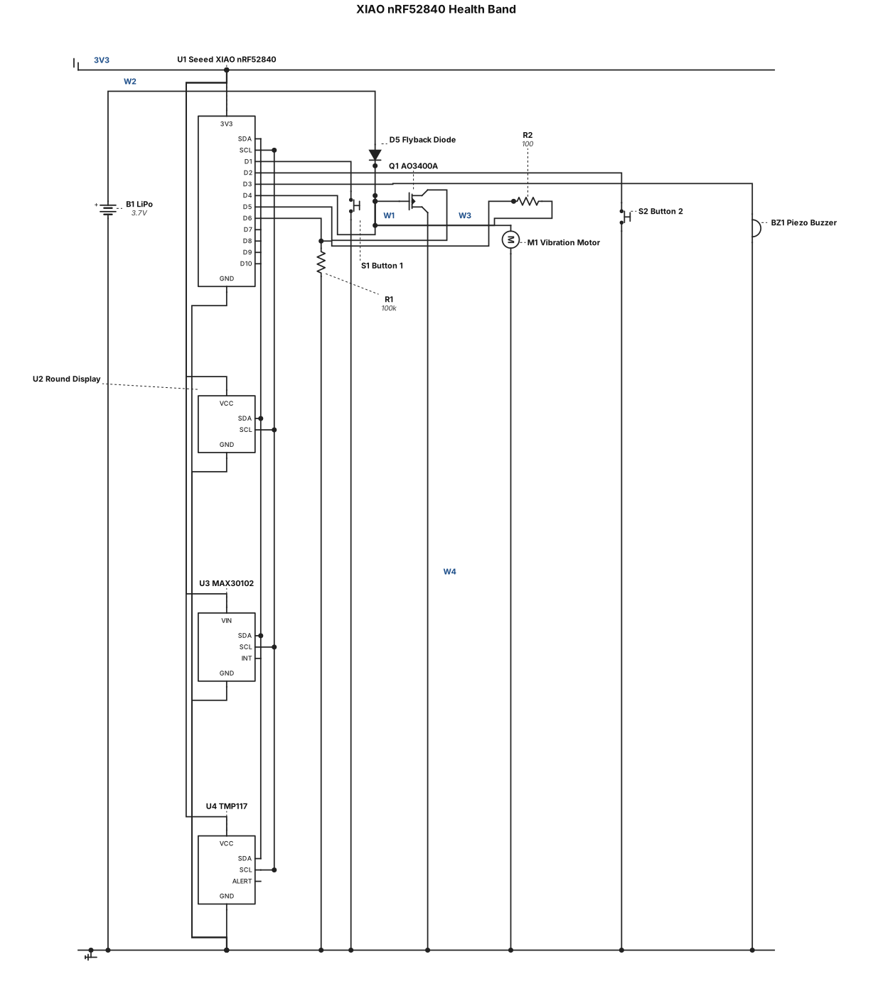
Here are all 13 components in the circuit: Seeed XIAO nRF52840 Seeed Round Display (XIAO header stack) MAX30102 heart-rate and SpO₂ sensor TMP117 temperature sensor Button 1 (6×6 mm) Button 2 (6×6 mm) Piezo buzzer Coin vibration motor (8–10 mm) AO3400A N-channel MOSFET Motor flyback diode 3.7 V LiPo battery MOSFET gate pull-down resistor (100 kΩ) MOSFET gate series resistor
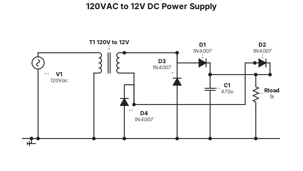
A tranformer to step down 120VAC power to 12V and a full wave bridge rectifier to rectify AC
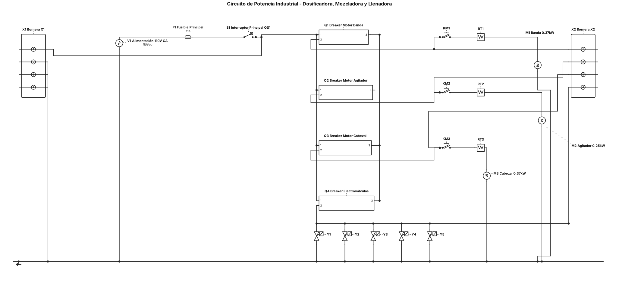
Diseña el circuito de potencia industrial de una máquina automática dosificadora, mezcladora y llenadora. Alimentación 110 V CA. Incluir interruptor principal, breakers, contactores KM1, KM2 y KM3, relés térmicos RT1, RT2 y RT3, motor M1 de banda 0,37 kW, motor M2 agitador 0,25 kW y motor M3 de cabezal 0,37 kW. Incluir electroválvulas Y1 a Y5 de 110 V CA y borneras. Utilizar simbología IEC y mostrar claramente las conexiones de potencia
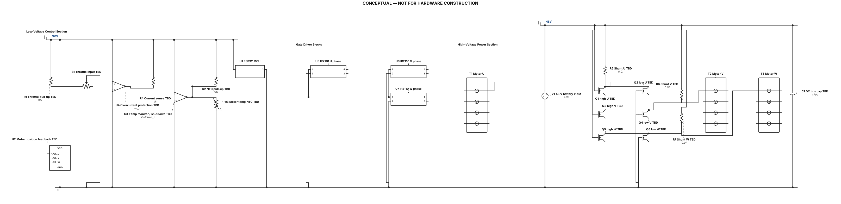
Create a conceptual electronic schematic for a Portable Emergency BLDC Motor Controller for a 48 V electric scooter. Show these functional blocks with standard electronic symbols and clear labels: 1. ESP32 microcontroller 2. Throttle input 3. Motor position feedback input 4. Three-phase inverter with six N-channel MOSFETs 5. Three IR2110 gate-driver blocks 6. Current-sensing and overcurrent protection block 7. Temperature monitoring and emergency shutdown 8. DC supply input and three motor outputs labelled U, V, W. Separate the low-voltage control section from the high-voltage power section. Label all functional connections. Mark unverified pin connections and component values as TBD. Do not invent connections. Title the drawing "CONCEPTUAL — NOT FOR HARDWARE CONSTRUCTION".
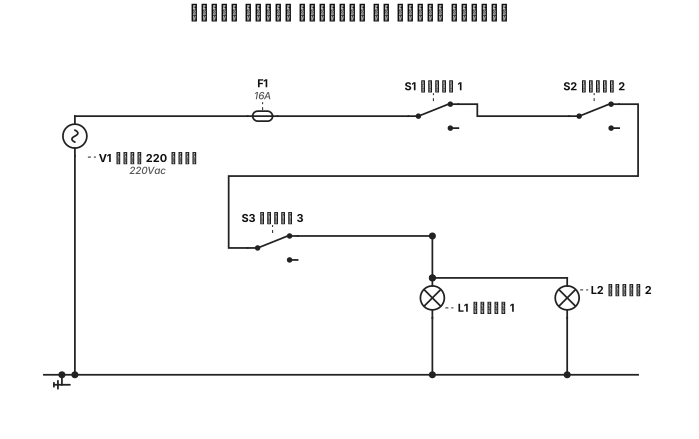
دائرة لتشغيل مصباحين من ثلاثة مفاتيح
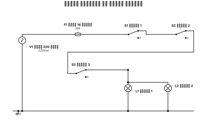
دائرة لتشغيل مصباحين من ثلاثة مفاتيح بالرسم التنفيذي
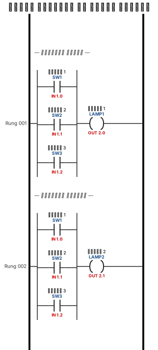
دائرة لتشغيل مصباحين من ثلاثة مفاتيح
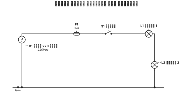
دائرة لتشغيل مصباحين على التوالي
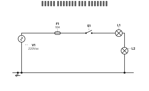
دائرة ل تشغيل مصباحين على التوالي
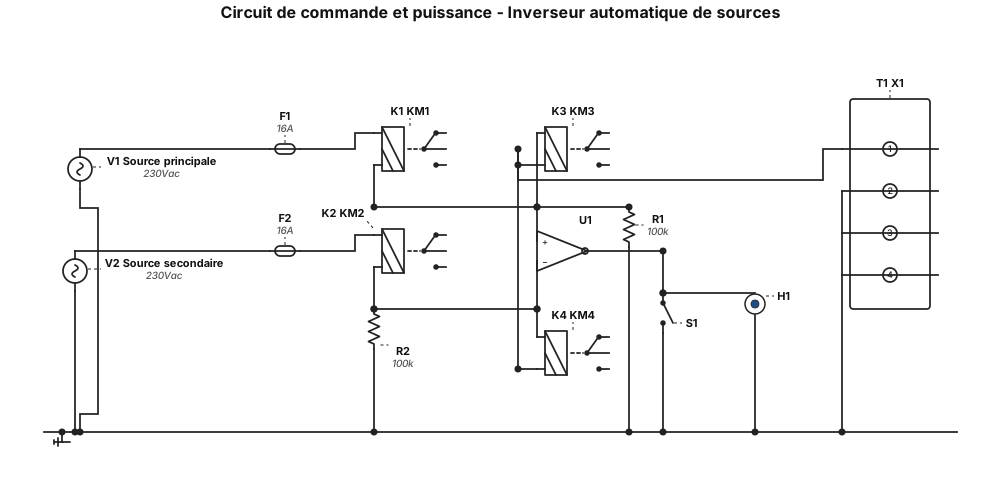
Schématisez le circuit de commande et puissance d'un inverseur automatique des sources de tension, avec repérage
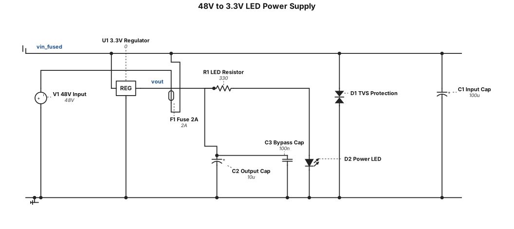
circuit converts 48v to 3,3 v and power to led with all the necessary circuit like the protection
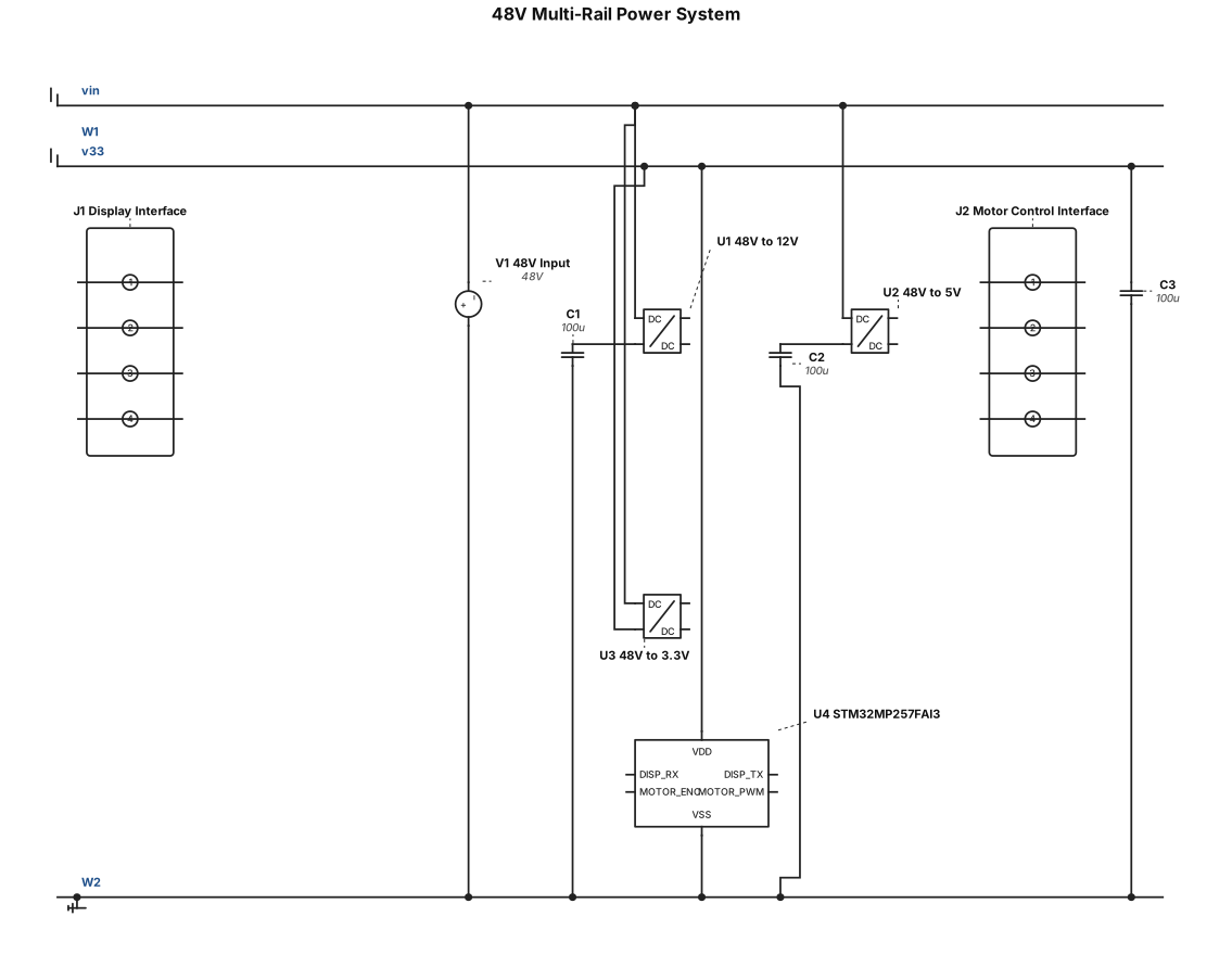
The system operates on a 48 V input, which is converted into 12 V, 5 V, and 3.3 V power rails. The 3.3 V rail supplies power to the STM32MP257FAI3 processor, which serves as the central controller and provides communication interfaces for the display and motor control systems.The system operates on a 48 V input, which is converted into 12 V, 5 V, and 3.3 V power rails. The 3.3 V rail supplies power to the STM32MP257FAI3 processor, which serves as the central controller and provides communication interfaces for the display and motor control systems.
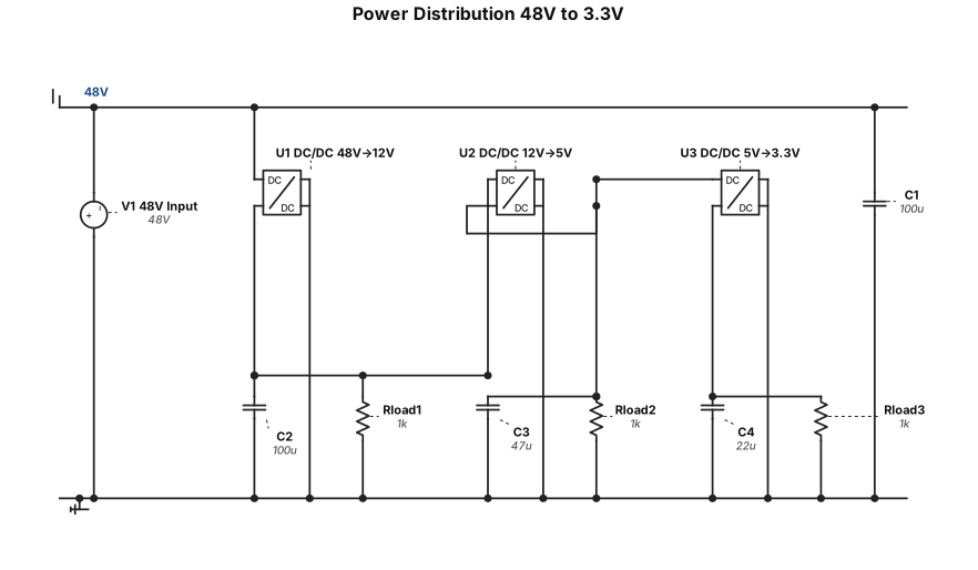
The system receives a 48 V input, which is converted through a DC/DC converter to the required low-voltage rails like 12 V, 5 V and 3.3 V rails. The proposed power hierarchy is therefore: 48 V Input → DC/DC Converter → 12 V → 5 V → 3.3 V The final voltage architecture should be confirmed based on the actual requirements of the MPU, communication transceivers, sensors, display and other loads.
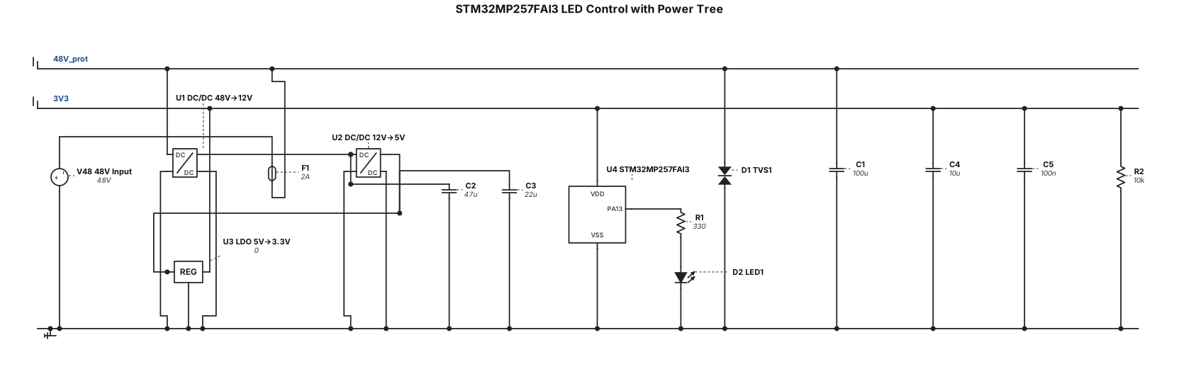
a circuit with STM32MP257FAI3 processor with actual pin outs and the input 3,3 V and it suppose to controller the LED on and Off. also put the over voltage protection as well. The system receives a 48 V input, which is converted through a DC/DC converter to the required low-voltage rails like 12 V, 5 V and 3.3 V rails. The proposed power hierarchy is therefore: 48 V Input → DC/DC Converter → 12 V → 5 V → 3.3 V The final voltage architecture should be confirmed based on the actual requirements of the MPU, communication transceivers, sensors, display and other loads.
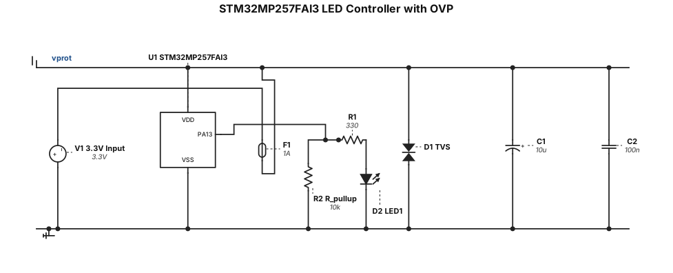
a circuit with STM32MP257FAI3 processor with actual pin outs and the input 3,3 V and it suppose to controller the LED on and Off. also put the over voltage protection as well.
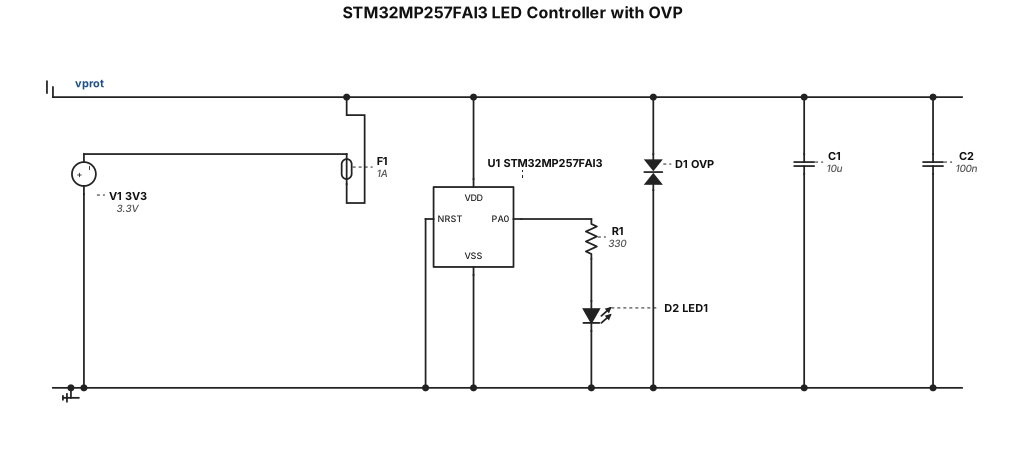
a circuit with STM32MP257FAI3 processor with the input 3,3 V and it suppose to controller the LED on and Off. also put the over voltage protection as well.
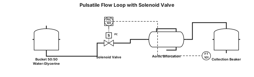
The experimental setup incorporates a pulsatile flow loop generated by a solenoid valve pulsed a frequency of 1.25 Hz. This frequency is chosen as it incapsulates a full cardiac cycle of 0.8s. A bucket filled with a mixture of 50:50 (water: glycerine) is used to house the fluid before entering the flow loop. The flow loop is comprised of clear tubing that extends from the bucket to the aortic bifurcation. The flow loop is filled to capacity with fluid to ensure there are minimal air bubbles in the system. A beaker/graduated flask is placed at the end of the flow loop to collect the fluid after 60 seconds have elapsed after the valve is opened. The discharged fluid is collected and poured back into the bucket to maintain a constant pressure head. The inlet boundary condition is pressure, and the outlet boundary condition is mass flow rate.