
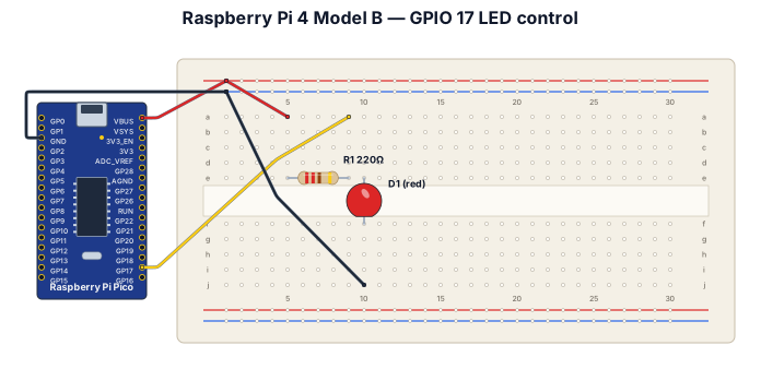
Create a breadboard wiring diagram showing a "Raspberry Pi 4 Model B" connected to a breadboard, with GPIO 17 controlling a red LED through a 220-ohm resistor. Must remember the board is "Raspberry Pi 4 Model B" not pico
ENGINEERING DRAWING ARCHIVE · REAL SPECS
Engineering Diagram Examples from Real Specifications
Browse eligible circuit, ladder, single-line, P&ID, breadboard, timing, and logic drawings with their original prompts.
Browse 549 real creationsCOMMUNITY OUTPUTS · EXACT PROMPTS
All visitor creations
Showing 409–432 of 549. No stock examples or system defaults. Choose a tool, study a real result, then reopen its prompt as your starting point.
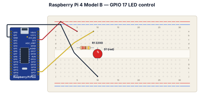
Create a breadboard wiring diagram showing a "Raspberry Pi 4 Model B" connected to a breadboard, with GPIO 17 controlling a red LED through a 220-ohm resistor.
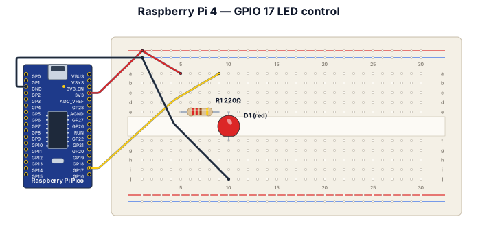
Create a breadboard wiring diagram showing a Raspberry Pi 4 Model B connected to a breadboard, with GPIO 17 controlling a red LED through a 220-ohm resistor.
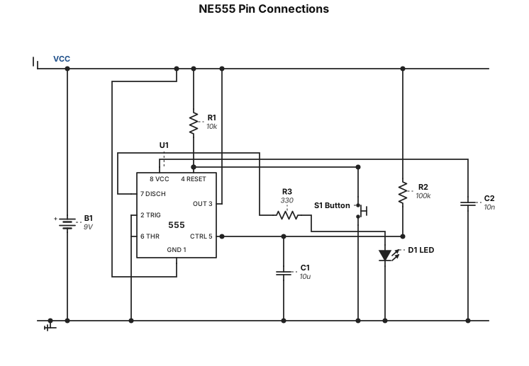
NE555 के पिन कनेक्शन पिन कनेक्शन 1 (GND) बैटरी का नेगेटिव (−) 8 (VCC) बैटरी का पॉजिटिव (+) 4 (RESET) पिन 8 / पॉजिटिव 2 (TRIGGER) 10 kΩ से पॉजिटिव; बटन से GND 6 (THRESHOLD) पिन 7 और टाइमिंग नोड से जुड़ा 7 (DISCHARGE) टाइमिंग रेज़िस्टर और पिन 6 के नोड से जुड़ा 3 (OUTPUT) 330 Ω रेज़िस्टर → LED का लंबा पैर; LED का छोटा पैर GND 5 (CONTROL) 10 nF कैपेसिटर से GND (वैकल्पिक, बेहतर स्थिरता के लिए)
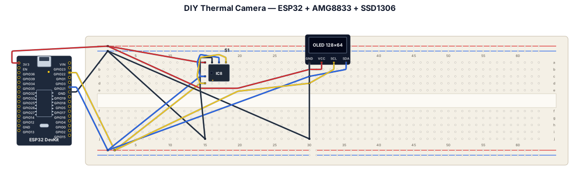
Create a realistic, beginner-friendly breadboard wiring diagram for a DIY thermal camera. COMPONENTS: 1. ESP32 DevKit V1 (ESP-WROOM-32) 2. AMG8833 Grid-EYE 8×8 infrared thermal sensor breakout module 3. SSD1306 0.96-inch monochrome OLED display, 128×64, I2C, 4 pins 4. One solderless breadboard 5. Male-to-male jumper wires NO SOLDERING. All modules must have pre-installed header pins compatible with the breadboard. EXACT CONNECTIONS: ESP32 3V3 → AMG8833 VIN/VCC and OLED VCC ESP32 GND → AMG8833 GND and OLED GND ESP32 GPIO21 → AMG8833 SDA and OLED SDA ESP32 GPIO22 → AMG8833 SCL and OLED SCL Use the ESP32's 3.3V supply. Verify the voltage requirements and pin labels of the actual breakout modules before building. DIAGRAM REQUIREMENTS: - Show the actual ESP32 DevKit V1 board and its labeled pins. - Show a full-size solderless breadboard. - Show the AMG8833 sensor module and SSD1306 OLED module. - Use red wires for 3.3V, black wires for GND, blue wires for SDA, and yellow wires for SCL. - Clearly label every connection and GPIO number. - Route wires neatly and avoid crossing wires where possible. - Show both I2C devices connected in parallel to the same SDA and SCL lines. - Do not invent extra components or connections. - If a component pinout cannot be verified, mark it as requiring verification. OUTPUT: Generate a physical breadboard layout, not just a symbolic electrical schematic. Include a pin-to-pin wiring table below the diagram. Make the diagram readable for a beginner assembling the circuit without soldering. This is a reference design. Do not claim the circuit has been physically tested.
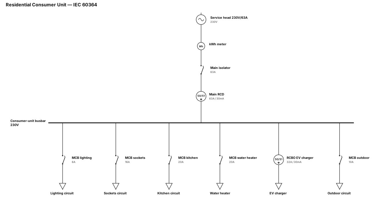
A 230 V residential consumer unit with a meter, 63 A main isolator, 30 mA RCD, busbar, and separate breakers for lighting, sockets, kitchen, water heater, EV charger, and outdoor circuit.
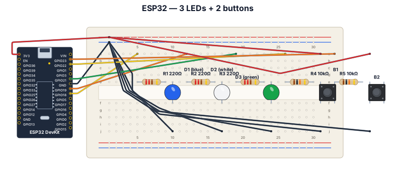
A ESP32 development board, wired to 3 leds (blue, white, green) through pins D18, 19 & 21, passing to ground through 220ohm resistors. Pins D22 & 23 go out to 2 buttons, these go to ground through 10kohms resistors. The board outputs positive current via 3v3, this only powers the buttons.
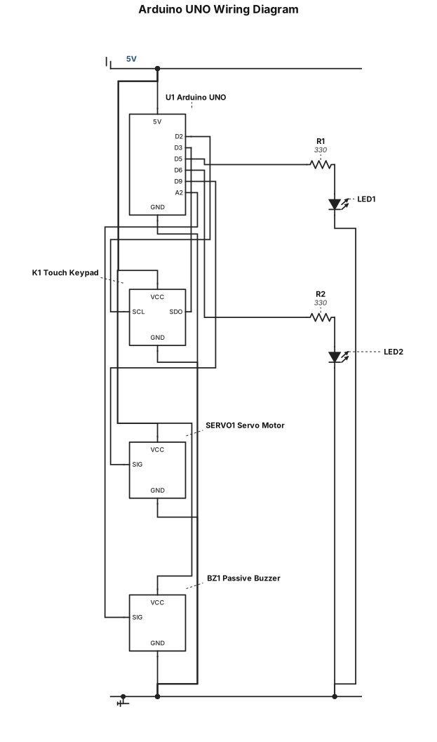
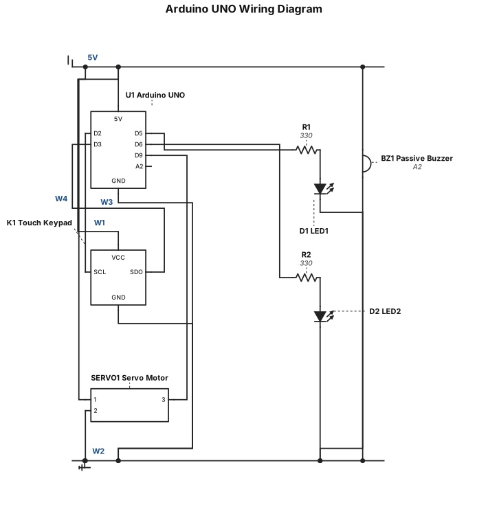
Create a clean, accurate Arduino UNO wiring diagram that fits on a single A4 sheet in landscape orientation. Use realistic electronic components, a white background, and a neat, uncluttered layout with clearly visible pin labels and wires. Connect the 4-pin touch keypad as follows: VCC to Arduino 5V, GND to GND, SCL to D2, and SDO to D3. Connect two LEDs to Arduino D5 and D6, each with its own 330-ohm series resistor and its cathode connected to GND. Connect the servo motor's power wire to 5V, ground wire to GND, and signal wire to D9. Connect the 3-pin passive buzzer module's VCC to 5V, GND to GND, and signal pin (SIG/S) to A2. Use red wires for 5V, black for GND, and different colors for signal wires. Arrange components around the Arduino with short, orderly wires and minimal crossings. Clearly label every connection and ensure that wires do not obscure pins or components. Follow the specified connections exactly. Do not add or change any connections, omit components, or create short circuits between 5V and GND. Prioritize electrical accuracy and readability. Generate a practical, component-based wiring illustration, not an abstract schematic, and ensure the complete diagram fits within the A4 page margins.
I have an Arduino UNO circuit. This circuit uses 2 LEDs, a passive buzzer, a servo motor, an Arduino UNO, and a touch keypad. The connections in this circuit are as follows: The VCC pin of the touch keypad is connected to any 5V pin on the Arduino. The GND pin is connected to any GND pin on the Arduino. The SCL pin is connected to Arduino pin D2, and finally, the SDO pin is connected to Arduino pin D3. This completes the connections for the touch keypad. For the LEDs, the connections are made to Arduino UNO pins D5 and D6, with a 330-ohm resistor connected in series with each LED for protection. For the servo motor, its power connections are supplied through the 5V and GND pins of the Arduino UNO, while its signal connection is made through Arduino pin D9. For the buzzer, a 3-pin passive buzzer module is used. Its power is supplied through the Arduino's 5V and GND pins, and its signal connection is made through Arduino pin A2. Based on these connections, create an image of the Arduino UNO wiring diagram for this circuit, ensuring that the entire diagram fits within the dimensions of an A4 sheet of paper.
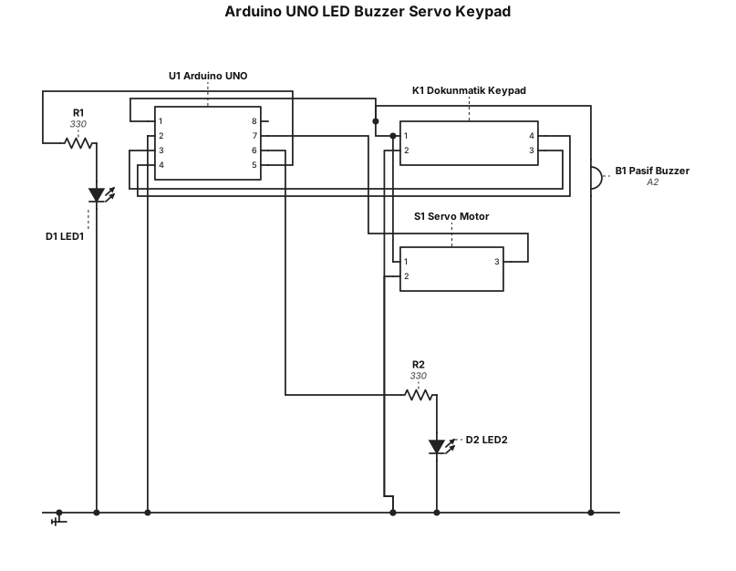
Elimde bir adet arduino UNO devresi var. Bu devrede 2 adet LED, pasif buzzer, Servo motor, Arduino UNO ve dokunmatik keypad kullanılmaktadır. Bu devrenin bağlantılarında: Dokunmatik Keypad'in VCC bacağı Arduino'nun herhangi bir 5V pinine bağlanmakta. GND bacağı ise Arduino'nun herhangi bir GND pinine bağlı. SCL bacağı ise Arduino D2 pinine bağlı, ve son olarak SDO bacağı Arduino'nun D3 pinine bağlıdır. Dokunmatik keypad için bağlantılar bu şekilde tamamlanır. LED'lerde ise bağlantı, Arduino UNO'nun D5 ve D6 pinlerine, seri bağlantılı bir 330ohm Direnç ile korunarak yapılmaktadır. Servo motorda ise, Servo motorun beslemeleri Arduino UNO'nun 5V ve GND. pinleri üzerinden, haberleşmesi ise Arduino D9 pini ile yapılmaktadır Buzzer bağlantıları ise, burada 3 bacaklı bir Pasif Buzzer Modülü kullanılmıştır. Beslemeleri Arduino'nun 5V ve GND pinleri üzerinden sağlanıp, haberleşme ise Arduino A2 pini üzerinden sağlanmaktadır. Bu bağlantılara dayanarak, bu devrenin Arduino UNO bağlantı şemasını bir A4 kağıdı boyutları içerisinde sığacak şekilde görselini oluşturunuz.
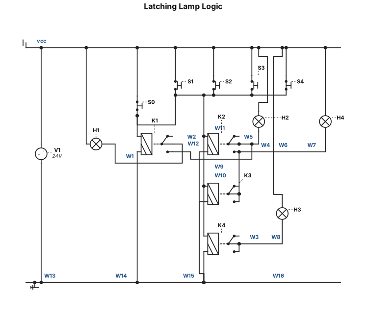
S0, S1, S2, S3, S4 – buttons/switches; H1, H2, H3, H4 – indicator lamps. Once the buttons are released, the lamps remain lit (with the exception of S4). H2 cannot be lit unless H1 is on; H3 cannot be lit unless both H1 and H2 are on. Implement the following logic: Releasing S0 turns on H3: H3 = !S0 Pressing S1 turns on H1: H1 = S1 Pressing S1 and S2 simultaneously turns on H2: H2 = S1 * S2 Pressing S1, S2, and S3 simultaneously turns on H4: H4 = S1 * S2 * S3 Pressing S4 turns off all lamps (i.e., it deactivates the latching circuits).
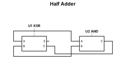
Half adder
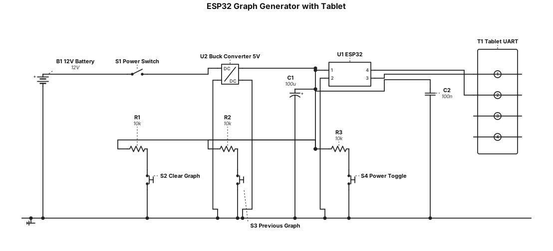
I want to make a graph generator i enter the equation on the tablet and esp32 on breadboard process it and shows its graph on the tablet with range and domain. Make its Circuit diagram on bread board use dc dc buck convertor to power it . Connect 3 buttons so that one is to remove the old graph and fresh new page for graph is there, one is to show previous graph and one is switch on and switch off one
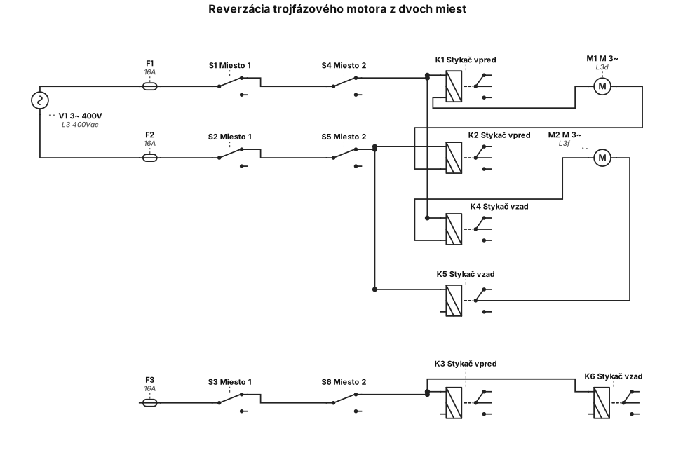
zapojenie reverzácie trojfazoveho motora z dvoch miest
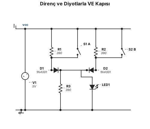
Direnç ve Diyotlarla Yapılan ‘VE’ (AND) Kapısı 1. Deneyde kullanılacak malzemeler Eleman Değeri Sayısı Diyot 1N4001 2 Direnç 390 3 LED 3 2. Deneyin Bağlantı Şeması 3. Deneyin Yapılışı Yukarıda bağlantı şeması gösterilen devreyi board üzerine kurunuz. Devreye +5V luk gerilimi uygulayınız. A ve B anahtarlarının değerlerini değiştirerek C çıkışını gözleyiniz ve aşağıdaki tabloyu doldurunuz.
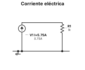
Calcule la corriente en amperes cuando 690 C de carga pasan por un punto dado en 2 min.
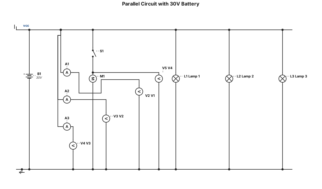
parallel ciruit diagram with 30V battery includes 3 lamps within ammeter and voltmeter in each lamp in which are first loop, the second loop includes motor and open switch and voltmeter includes in third branch
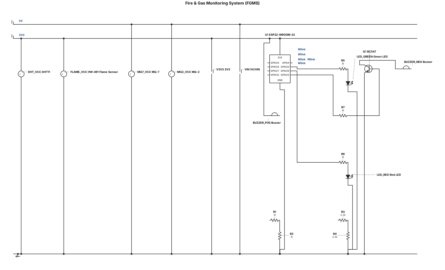
Project: Fire & Gas Monitoring System (FGMS) Controller: ESP32-WROOM-32, 38-pin board, 3.3V logic. Sensors and connections: - MQ-2: VCC → 5V/VIN; GND → common GND; AO → 1kΩ resistor → junction → GPIO34; junction → 1kΩ resistor → GND. - MQ-7: VCC → 5V/VIN; GND → common GND; AO → 3.3kΩ resistor → junction → GPIO35; junction → 3.3kΩ resistor → GND. - HW-491 Flame Sensor: VCC → 3V3; GND → common GND; DO → GPIO27; AO → GPIO32. - DHT11: VCC → 3V3; GND → common GND; DATA → GPIO4. Outputs: - Green LED: GPIO33 → 1kΩ resistor → LED anode; cathode → GND. - Red LED: GPIO26 → 1kΩ resistor → LED anode; cathode → GND. - Buzzer: GPIO25 → 1kΩ resistor → BC547 base; emitter → GND; collector → buzzer negative; buzzer positive → 3V3. GPIO map: GPIO4=DHT11; GPIO25=buzzer; GPIO26=red LED; GPIO27=flame DO; GPIO32=flame AO; GPIO33=green LED; GPIO34=MQ-2 AO; GPIO35=MQ-7 AO. Diagram requirements: Draw the ESP32 centrally, sensors and outputs around it, standard electronic symbols, clearly labelled GPIOs, resistor values, power rails and common ground. Show both voltage dividers with ADC connections at their midpoints. Use neat, non-crossing wires. Do not invent components or change pin assignments. Safety: Never connect 5V directly to ESP32 GPIOs. Verify the BC547 pinout and actual module labels before powering.

Diseña un circuito lógico combinacional editable para simular en Proteus ISIS. Debe convertir cuatro entradas binarias A, B, C y D en un dígito mostrado en un display de siete segmentos 5161AS de cátodo común. Tabla de verdad: 0000 → 0 0001 → 1 0010 → 1 0011 → 2 1100 → 2 1101 → 3 1110 → 3 1111 → 4 Trata las otras ocho combinaciones como condiciones indiferentes (don't care), ya que no se utilizarán. Utiliza exclusivamente compuertas lógicas NOT, AND y OR; no uses microcontroladores ni decodificadores integrados. Incluye resistencias limitadoras, alimentación de 5 V y GND. Genera y simplifica las ecuaciones de los segmentos a, b, c, d, e, f y g mediante mapas de Karnaugh. Comprueba las ocho combinaciones definidas y explica cómo exportar el esquema a un formato compatible con Proteus ISIS. No entregues solamente una imagen: necesito un esquema editable con conexiones eléctricas reales. Utilizando puras compuertas lógicas
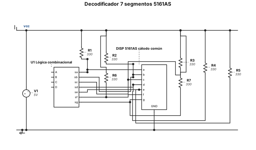
Diseña un circuito lógico combinacional Debe convertir cuatro entradas binarias A, B, C y D en un dígito mostrado en un display de siete segmentos 5161AS de cátodo común. Tabla de verdad: 0000 → 0 0001 → 1 0010 → 1 0011 → 2 1100 → 2 1101 → 3 1110 → 3 1111 → 4 Trata las otras ocho combinaciones como condiciones indiferentes (don't care), ya que no se utilizarán. Utiliza exclusivamente compuertas lógicas NOT, AND y OR; no uses microcontroladores ni decodificadores integrados. alimentación de 5 V y GND. Comprueba las ocho combinaciones definidas
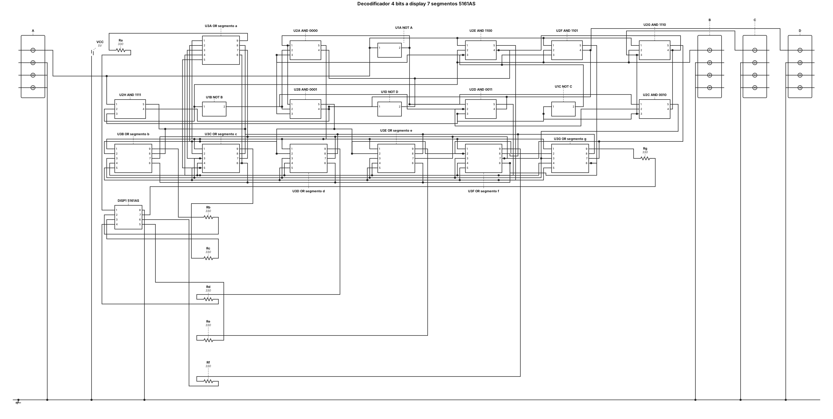
Diseña un circuito lógico combinacional editable para simular en Proteus ISIS. Debe convertir cuatro entradas binarias A, B, C y D en un dígito mostrado en un display de siete segmentos 5161AS de cátodo común. Tabla de verdad: 0000 → 0 0001 → 1 0010 → 1 0011 → 2 1100 → 2 1101 → 3 1110 → 3 1111 → 4 Trata las otras ocho combinaciones como condiciones indiferentes (don't care), ya que no se utilizarán. Utiliza exclusivamente compuertas lógicas NOT, AND y OR; no uses microcontroladores ni decodificadores integrados. Incluye resistencias limitadoras, alimentación de 5 V y GND. Genera y simplifica las ecuaciones de los segmentos a, b, c, d, e, f y g mediante mapas de Karnaugh. Comprueba las ocho combinaciones definidas y explica cómo exportar el esquema a un formato compatible con Proteus ISIS. No entregues solamente una imagen: necesito un esquema editable con conexiones eléctricas reales.
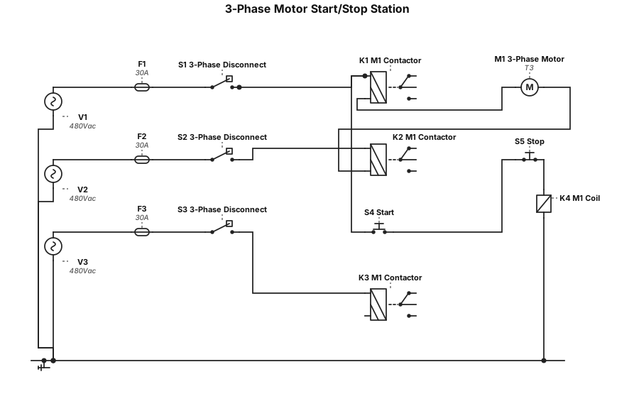
Starting at the 3-phase disconnect draw a Start / Stop Station (S/S) controlling a motor. You will wire up the circuit (if it is correct) on the trainers.
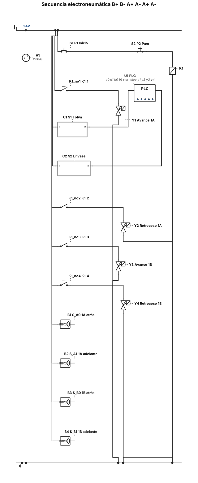
2. Secuencia de funcionamiento La notación abreviada de un ciclo es: **B+ → B− → A+ → A− → A+ → A−** Donde: - **A+**: avance del cilindro 1A. - **A−**: retroceso del cilindro 1A. - **B+**: avance del cilindro 1B. - **B−**: retroceso del cilindro 1B. ## 3. Consideraciones adicionales - Los cilindros deberán utilizar únicamente sensores electromagnéticos para la detección de sus posiciones. - En la simulación realizada en FluidSIM, los sensores de la base de la tolva y de la caserina estarán activos mientras exista material y permanecerán inactivos cuando no haya material. - Si ocurre un fallo en el suministro de energía eléctrica, los cilindros deberán regresar a su posición inicial. ## 4. Elementos principales del sistema - Dos cilindros neumáticos de doble efecto: 1A y 1B. - Electroválvulas para controlar el avance y retroceso de los cilindros. - Sensores electromagnéticos para detectar las posiciones de los cilindros. - Sensor capacitivo S1 para detectar la presencia de material en la tolva. - Sensor capacitivo S2 para detectar la condición de disponibilidad del siguiente envase. - Pulsador P1 para iniciar la secuencia. - Pulsador P2 para detener la secuencia. - Software FluidSIM para diseñar y simular el circuito electroneumático.
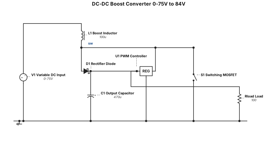
A DC circuit converter to convert A variable dc voltage ranged 0-75 v to constant 84v dc