
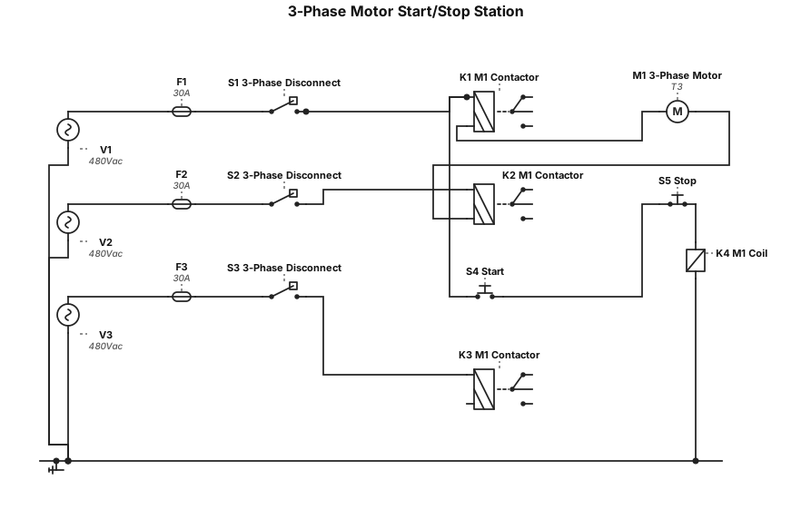
Starting at the 3-phase disconnect draw a Start / Stop Station (S/S) controlling a motor. You will wire up the circuit (if it is correct) on the trainers.
ENGINEERING DRAWING ARCHIVE · REAL SPECS
Engineering Diagram Examples from Real Specifications
Browse eligible circuit, ladder, single-line, P&ID, breadboard, timing, and logic drawings with their original prompts.
Browse 552 real creationsCOMMUNITY OUTPUTS · EXACT PROMPTS
All visitor creations
Showing 433–456 of 552. No stock examples or system defaults. Choose a tool, study a real result, then reopen its prompt as your starting point.
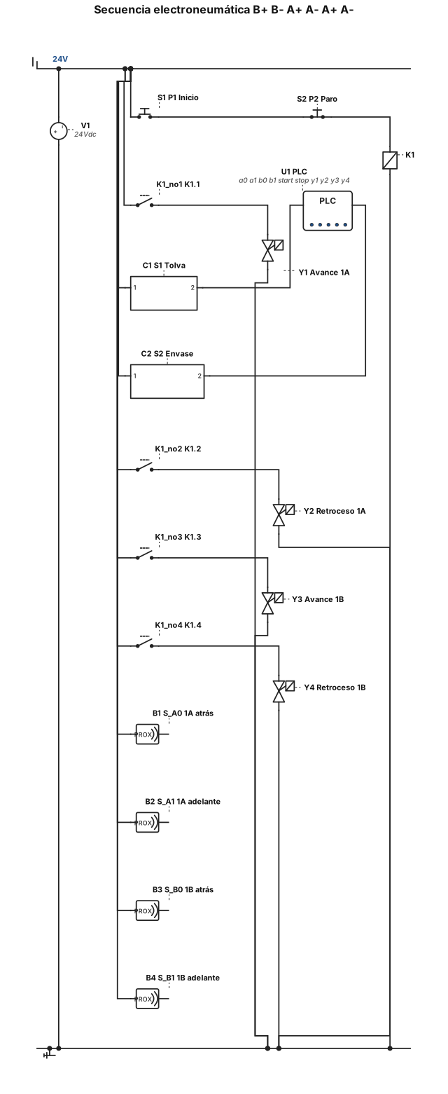
2. Secuencia de funcionamiento La notación abreviada de un ciclo es: **B+ → B− → A+ → A− → A+ → A−** Donde: - **A+**: avance del cilindro 1A. - **A−**: retroceso del cilindro 1A. - **B+**: avance del cilindro 1B. - **B−**: retroceso del cilindro 1B. ## 3. Consideraciones adicionales - Los cilindros deberán utilizar únicamente sensores electromagnéticos para la detección de sus posiciones. - En la simulación realizada en FluidSIM, los sensores de la base de la tolva y de la caserina estarán activos mientras exista material y permanecerán inactivos cuando no haya material. - Si ocurre un fallo en el suministro de energía eléctrica, los cilindros deberán regresar a su posición inicial. ## 4. Elementos principales del sistema - Dos cilindros neumáticos de doble efecto: 1A y 1B. - Electroválvulas para controlar el avance y retroceso de los cilindros. - Sensores electromagnéticos para detectar las posiciones de los cilindros. - Sensor capacitivo S1 para detectar la presencia de material en la tolva. - Sensor capacitivo S2 para detectar la condición de disponibilidad del siguiente envase. - Pulsador P1 para iniciar la secuencia. - Pulsador P2 para detener la secuencia. - Software FluidSIM para diseñar y simular el circuito electroneumático.
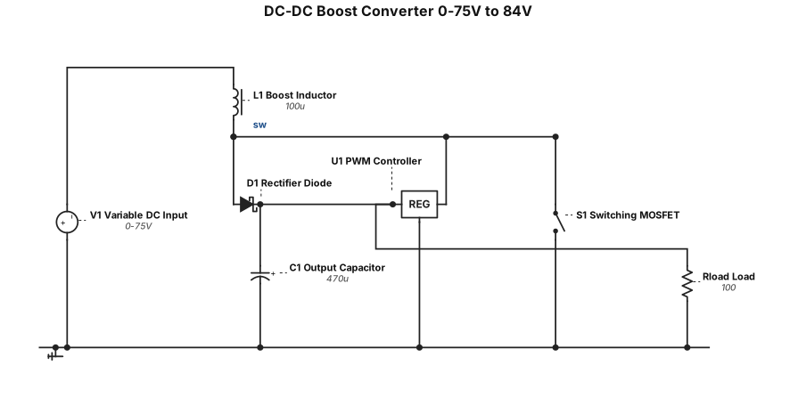
A DC circuit converter to convert A variable dc voltage ranged 0-75 v to constant 84v dc
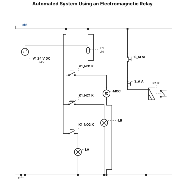
Title: Automated System Using an Electromagnetic Relay Draw a complete electrical control circuit (schéma électrique développé) using standard IEC electrical symbols. Components: - M: Normally open START pushbutton. - A: Normally closed STOP pushbutton. - K: One monostable electromagnetic relay with a 24 V DC coil. - LR: Red indicator lamp, 24 V DC. - LV: Green indicator lamp, 24 V DC. - MCC: 24 V DC motor. - Power supply: 24 V DC. Operating requirements: 1. Initial state: When neither pushbutton is operated, the red lamp LR is ON, the green lamp LV is OFF, and the DC motor MCC is STOPPED. 2. START operation: When the START pushbutton M is pressed, the electromagnetic relay K energizes. The red lamp LR turns OFF, the green lamp LV turns ON, and the DC motor MCC starts running. 3. STOP operation: When the STOP pushbutton A is pressed, the relay K de-energizes. The circuit returns to its initial state: the red lamp LR turns ON, the green lamp LV turns OFF, and the motor MCC stops. Drawing requirements: - Use a 24 V DC control and power supply. - Use one monostable electromagnetic relay K with suitable auxiliary contacts. - Show the relay coil and all normally open (NO) and normally closed (NC) contacts. - Clearly label all components: M, A, K, LR, LV, and MCC. - Draw the complete electrical schematic with clear, correct connections and standard IEC symbols. - Show the initial state and explain how the circuit changes when START and STOP are operated. - Do not use PLC ladder logic. Draw a conventional hardwired relay control circuit.
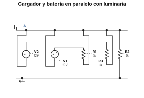
Un cargador (V1 en serie con R1) y una batería (V2 en serie con R3) se conectan en paralelo entre el nodo A y la referencia, junto con una luminaria R2. Los terminales positivos de ambas fuentes apuntan hacia el nodo A. Suponga las corrientes I1 (cargador) e I3 (batería) entrando al nodo A, e I2 saliendo de A por la luminaria.
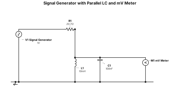
I need the circuit to be arranged as follows: first, a signal generator, followed by a 20.7 Ω resistor connected in series. After the resistor, there should be a node where the inductor (coil) and capacitor are connected in parallel. The millivoltmeter (mV meter) should be connected to this node to measure the voltage.
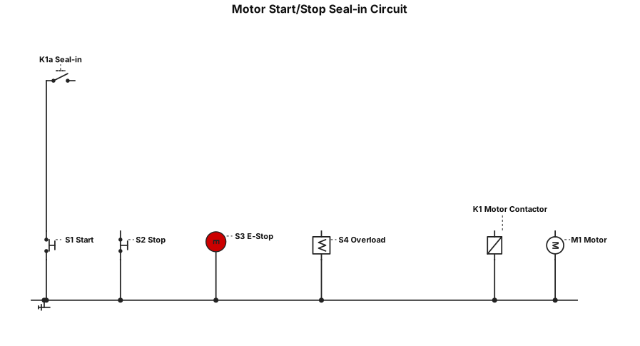
A PLC ladder diagram for a motor start/stop seal-in circuit with an emergency-stop interlock and an overload contact
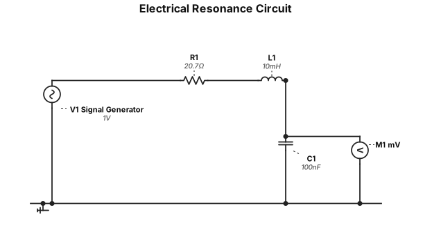
Create an electrical resonance circuit consisting of one signal generator, one 20.7 Ω resistor, one inductor (coil), one capacitor, and one millivoltmeter.
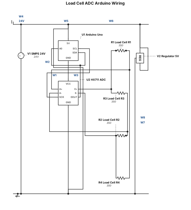
I am connecting loadcell with ADC and Arduino Uno. These will be powered from a SMPS. Created a professional electrical schematic wiring diagram between these components

Create a clean, professionally arranged digital logic circuit diagram for a four-floor elevator controller FSM, suitable for an engineering college presentation. Draw the FSM next-state logic using two D flip-flops from a 74HC74 IC. Label the state outputs S1 and S0, and the D inputs D1 and D0. Use these state assignments: IDLE = 00 UP = 01 DOWN = 10 DOOR OPEN = 11 Show the input signals LT, GT, EQ, R, and TD, with clearly labelled AND, OR, and NOT gates. Use these next-state equations: D1 = (IDLE AND R AND (GT OR EQ)) OR (UP AND EQ) OR DOWN OR (DOOR AND NOT TD) D0 = (IDLE AND R AND (LT OR EQ)) OR UP OR (DOWN AND EQ) OR (DOOR AND NOT TD) Show the common clock, reset, feedback from S1 and S0 to the state-decoding logic, and outputs for IDLE, UP, DOWN, and DOOR OPEN. Use a white background, standard digital logic symbols, readable labels, straight wires, minimal crossings, and a landscape layout. Do not invent additional components or change the equations.
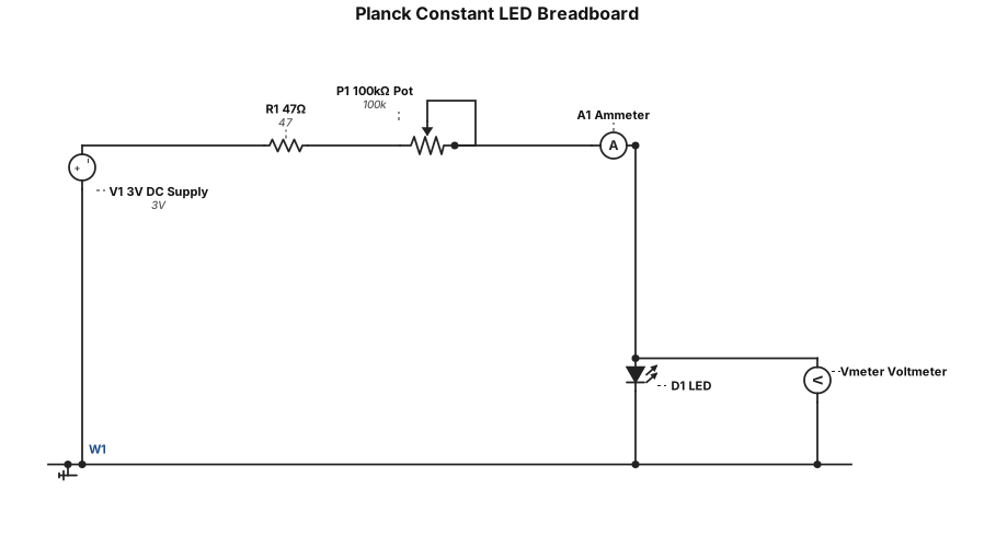
Create a realistic, clearly labelled, physical breadboard wiring layout for a Physics Laboratory experiment to determine Planck’s constant using the LED method. Components: - 3 V DC power supply - One forward-biased LED - One fixed current-limiting resistor between 10 Ω and 100 Ω - One potentiometer of 0–100 kΩ to vary the LED voltage/current - One ammeter connected in series to measure LED current - One voltmeter connected in parallel directly across the LED Connections: Connect the positive terminal of the 3 V supply through the fixed resistor, potentiometer, ammeter, and LED in a single series circuit, returning to the negative terminal. Arrange the ammeter in series with the LED. Connect the voltmeter’s positive probe to the LED anode and its negative probe to the LED cathode, so it measures only the voltage across the LED. The LED anode must face the positive supply side and the cathode must face the negative supply side. Layout requirements: Show a realistic solderless breadboard with actual component placement, red and black jumper wires, power rails, resistor, potentiometer, LED, and both meters. Label every component and clearly show each connection. Do not produce a schematic-only diagram. Do not add a photodiode. Keep the current below 3 mA, as specified in the lab procedure. Follow the described circuit connections exactly.
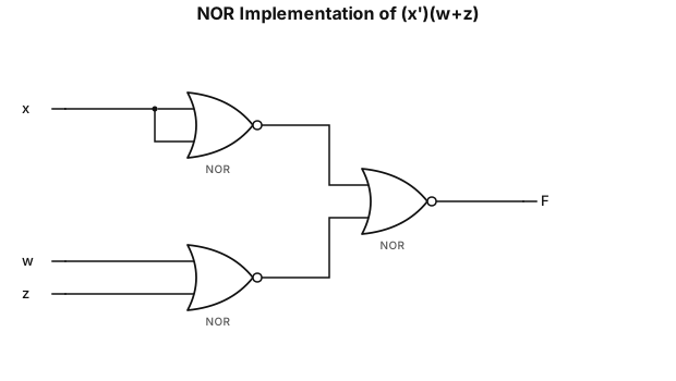
(x')(w+z) with 2 NOR only
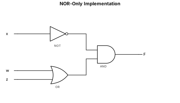
(x')(w+z) with least NOR only
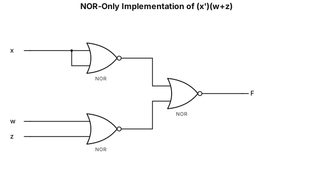
(x')(w+z) with NOR only
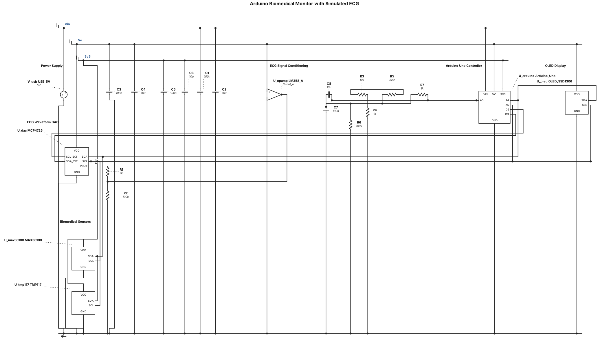
Generate a complete electronic circuit schematic for an Arduino-based biomedical monitoring system with simulated ECG signal conditioning. Requirements: Use an Arduino Uno as the main controller. Generate a simulated ECG waveform using Arduino code. Use an MCP4725 DAC to convert the digital waveform into an analog signal. Use an LM358 operational amplifier circuit to amplify and condition the simulated ECG signal. Connect the LM358 output to Arduino analog input A0 for sampling. Use a MAX30100 sensor to measure heart rate and estimate SpO₂. Use a TMP117 sensor to measure temperature. Use a four-pin OLED display (GND, VDD, SDA, SCK/SCL) to display sensor readings and simulated ECG information. Connect I²C devices using Arduino A4 (SDA) and A5 (SCL), after verifying voltage compatibility and address conflicts. Show all LM358 pin numbers, resistor and capacitor values, module connections, signal paths, power supply connections, and common ground. Use available components: 10 kΩ, 100 kΩ, 1 kΩ, and 220 Ω resistors; 100 nF and 10 µF capacitors. Identify any additional components required. Include a complete bill of materials and pin-to-pin connection table. Design the circuit for assembly on a general-purpose PCB, including component placement and solder-side wiring guidance. Verify amplifier gain, signal voltage ranges, power requirements, I²C compatibility, and Arduino input limits. Check for incorrect or missing connections and clearly identify any assumptions requiring verification. Make the schematic suitable for a beginner and use verified component datasheets. Provide a clear, labelled, editable electrical schematic with standard electronic symbols and connected wires, not merely a block diagram or decorative illustration.
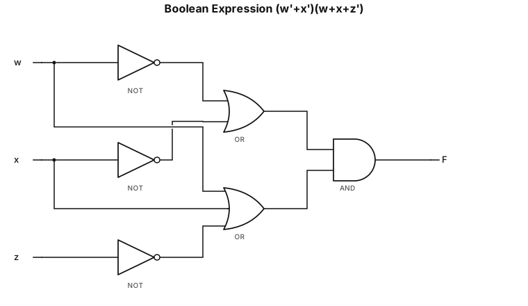
(w'+x')(w+x+z') without NOR
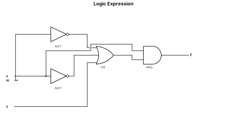
(x)(w'+x'+z) without NOR
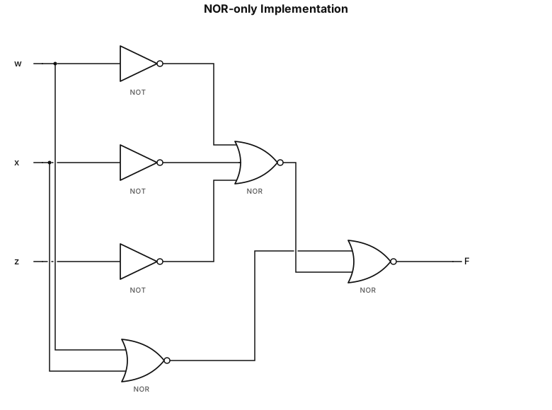
(w+x)(w'+x'+z) with NOR only
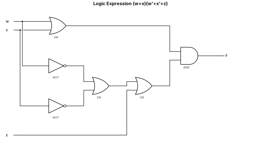
(w+x)(w'+x'+z) without NOR
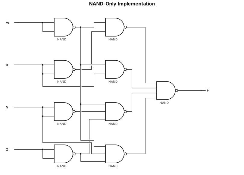
w'x' + w'x + w'y'z' + w'yz' with NAND only
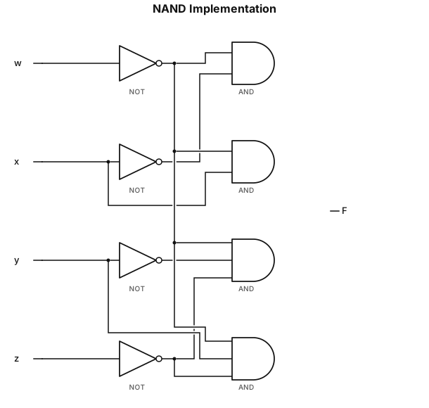
w'x' + w'x + w'y'z' + w'yz' with NAND
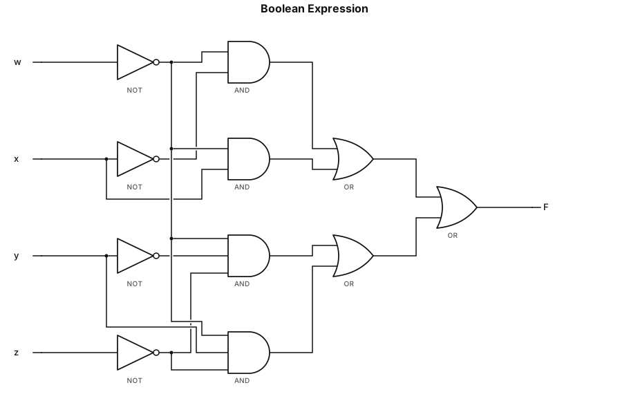
w'x' + w'x + w'y'z' + w'yz' without NAND
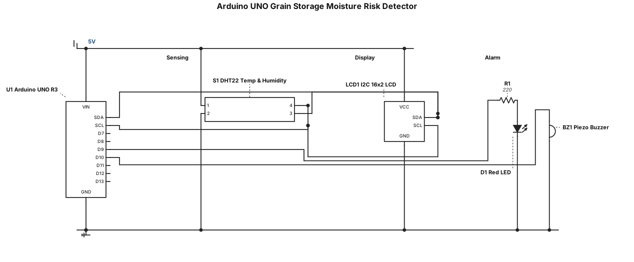
Create a beginner-friendly Arduino UNO circuit diagram for a Grain Storage Container with Moisture Risk Detection. Components: Arduino UNO R3, DHT22 temperature and humidity sensor, I2C 16x2 LCD, red LED, 220-ohm resistor, piezo buzzer, breadboard and jumper wires. Show every wire with exact Arduino pin numbers. Display temperature, relative humidity and risk status on the LCD. Turn on the LED and buzzer when temperature or humidity exceeds the set limits. Make the diagram simple for a beginner school project.
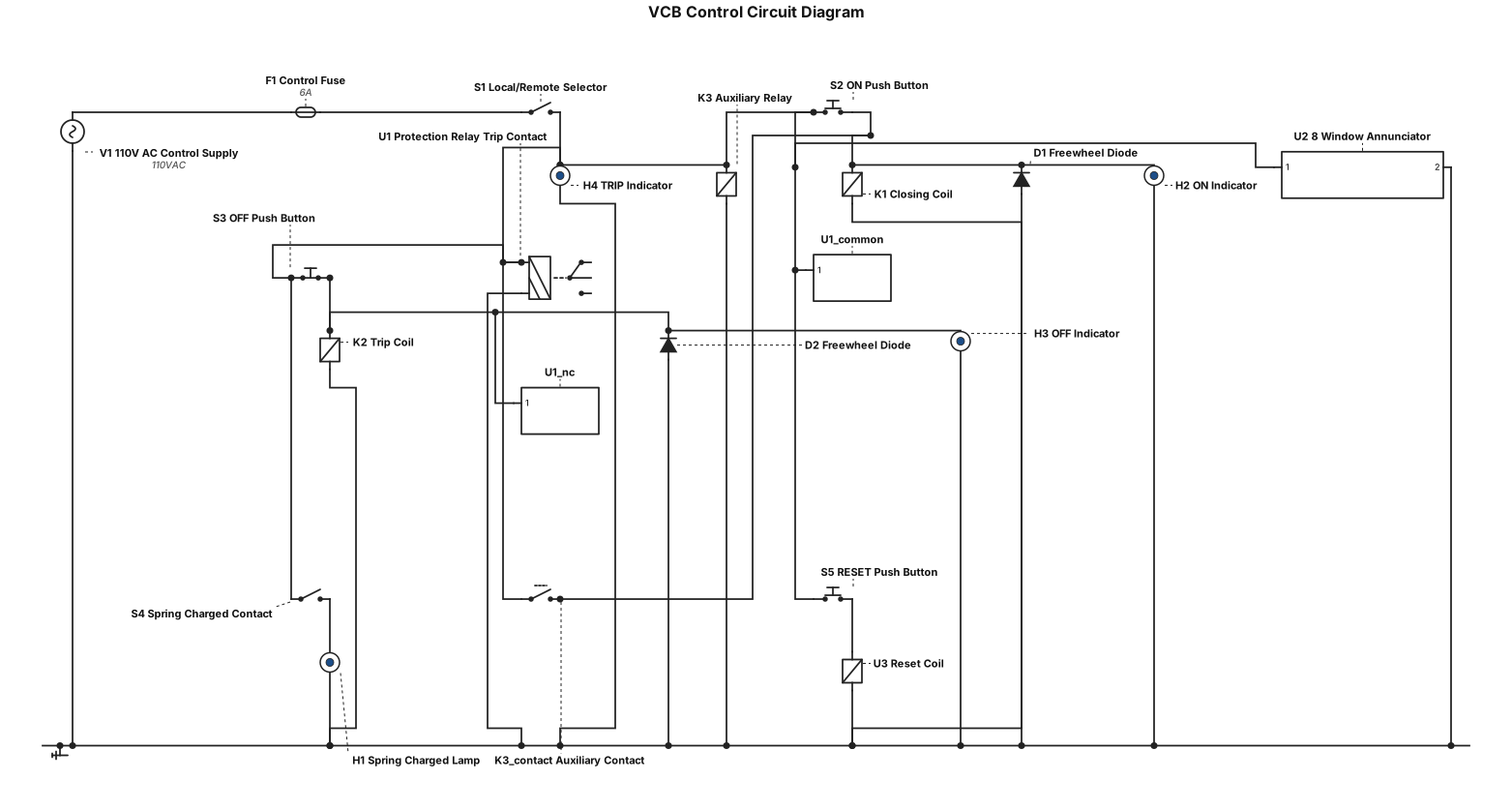
14/16 SWG sheet steel clad, dust and vermin proof, POWDER COATED, free standing, floor mounting indoor HT Switchgear 11KV, 50Hz, three phase, 800A hard drawn electrolytic copper busbars equipped with:1 No. 630 A, 11 KV, 20KA rated short time current, 50 Hz, electromagnetically operated/ spring charged stored energy mechanism with Fixed Type VCB, manual closing/ tripping device for emergency operation, maximum service voltage 12KV, short circuit breaking capacity 20KA, 110V DC/ 110VAC from PT for operating shunt tripping coil, mechanically ON/OFF/TRIP indicator. 2 Nos. Cast resin insulated, Double pole, Potential Transformer, ratio: 11/√3/0.110/√3 KV, Class 0.5, 100 VA. 1 No. MCB of adequate rating for PT Scondary protection. 3 Nos. Cast resin insulated, 11 KV dry type double core CT with Ratio: 50/5/5A, 1st core for metering, 2nd for protection Core 1 : 10 VA, Class 0.5M5 Core 2 : 15 VA, Class 10P10 3 Nos. Ammeter, 0 - 630A. 1 No. Voltmeter, 0 - 15KV, with selector switch1 No. Triple pole solid state micro-processor operated IDMT relay for over current, earthfault and short circuit protection with standard setting. 1 Nos. 8 windows Annunciator 3 Set ON/OFF/RESET Push Button 7 Nos. Indicating Lamps/ON/OFF/TRIP/Spring charged. now give a VCB Control Circuit Diagram.