
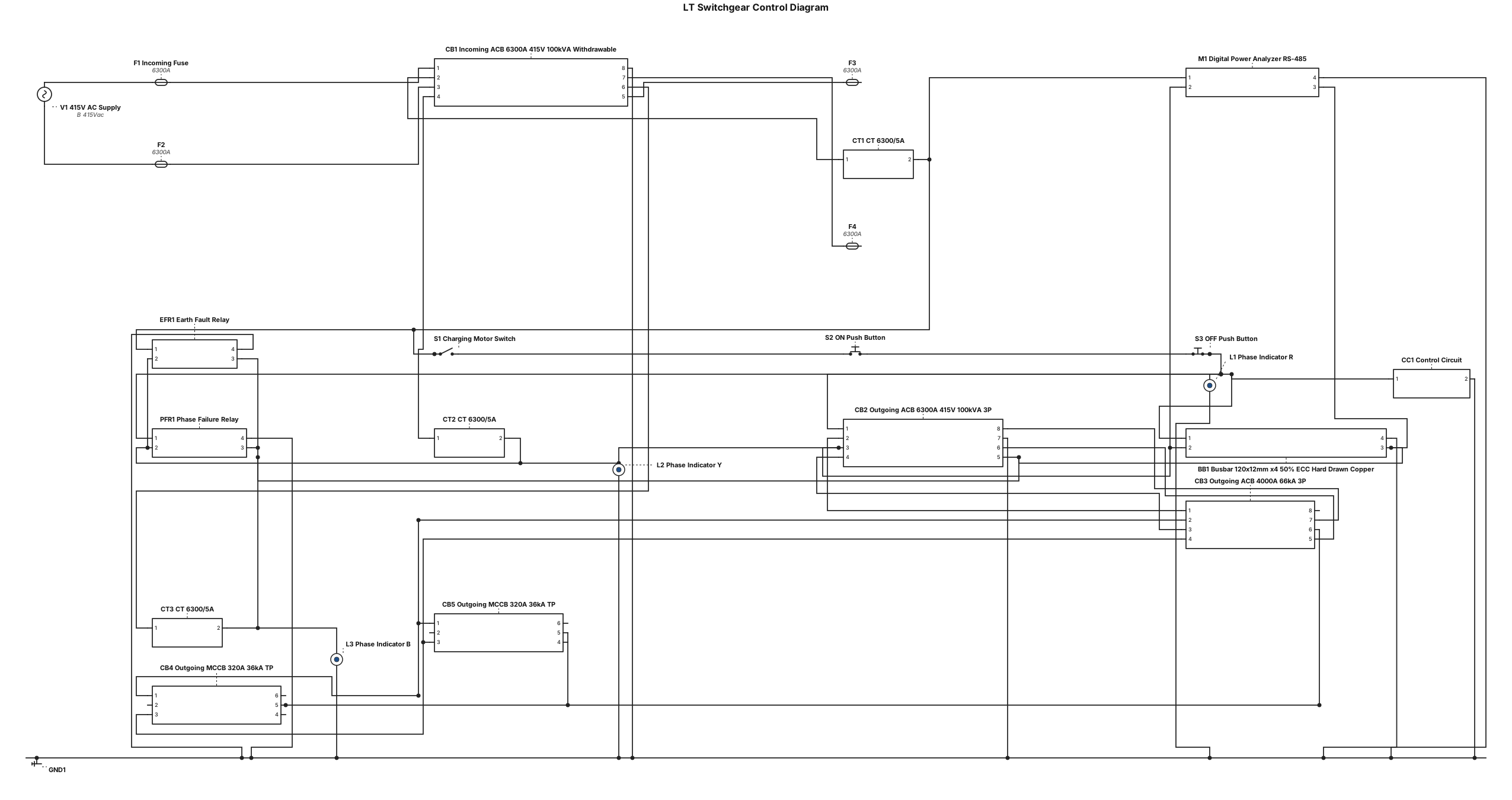
LT Switchgear with 9216A (Red, Yellow, Blue, Green) TPN, 50% ECC hard drawn copper busbar. Busbar size (120x12mmx4) with Incoming: 6300A, 415V, 100KVA withdrawable type ACB, 3 nos ct, ratio-6300/5A, 01 nos. Digital power analyzer meter with RS-485 Communication port (Amps, volt, hz, pf, kvar/kw/kwh/var), 1 nos. earth fault relay, 1 set charging motor switch, 1 set on off push switch, 3 nos. phase indicator lamp, 1 nos. phase failure relay, 1 set contol circuit. outgoing: 1 nos. 6300A, 415v, 100kva, 3p, withdrawable type ACB, 1 nos. 4000A, 66ka, 3p ACB, 2 nos. 320A, 36ka, tp mccb, now give me LT control diagram with small length, A4 Paper landscap.
ENGINEERING DRAWING ARCHIVE · REAL SPECS
Engineering Diagram Examples from Real Specifications
Browse eligible circuit, ladder, single-line, P&ID, breadboard, timing, and logic drawings with their original prompts.
Browse 552 real creationsCOMMUNITY OUTPUTS · EXACT PROMPTS
All visitor creations
Showing 457–480 of 552. No stock examples or system defaults. Choose a tool, study a real result, then reopen its prompt as your starting point.
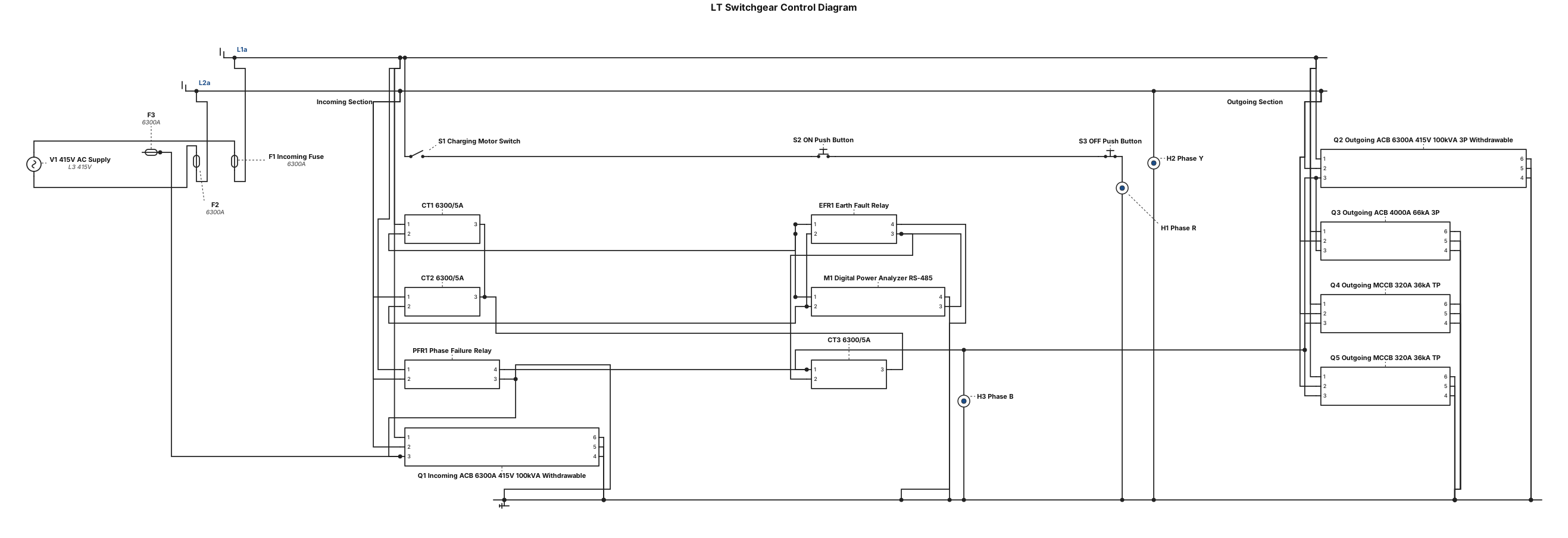
LT Switchgear with 9216A TPN, 50% ECC hard drawn copper busbar. Busbar size (120x12mmx4) with Incoming: 6300A, 415V, 100KVA withdrawable type ACB, 3 nos ct, ratio-6300/5A, 01 nos. Digital power analyzer meter with RS-485 Communication port (Amps, volt, hz, pf, kvar/kw/kwh/var), 1 nos. earth fault relay, 1 set charging motor switch, 1 set on off push switch, 3 nos. phase indicator lamp, 1 nos. phase failure relay, 1 set contol circuit. outgoing: 1 nos. 6300A, 415v, 100kva, 3p, withdrawable type ACB, 1 nos. 4000A, 66ka, 3p ACB, 2 nos. 320A, 36ka, tp mccb, now give me LT control diagram with A4 Paper langscap.
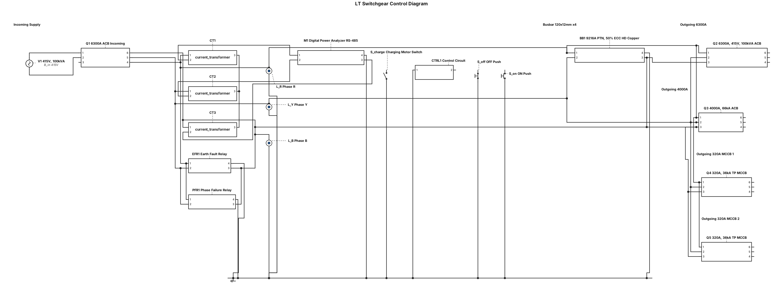
LT Switchgear with 9216A PTN, 50% ECC hard drawn copper busbar. Busbar size (120x12mmx4) with Incoming: 6300A, 415V, 100KVA withdrawable type ACB, 3 nos ct, ratio-6300/5A, 01 nos. Digital power analyzer meter with RS-485 Communication port (Amps, volt, hz, pf, kvar/kw/kwh/var), 1 nos. earth fault relay, 1 set charging motor switch, 1 set on off push switch, 3 nos. phase indicator lamp, 1 nos. phase failure relay, 1 set contol circuit. outgoing: 1 nos. 6300A, 415v, 100kva, 3p, withdrawable type ACB, 1 nos. 4000A, 66ka, 3p ACB, 2 nos. 320A, 36ka, tp mccb, now give me LT control diagram with A4 Papar.

LT Switchgear with 9216A PTN, 50% ECC hard drawn copper busbar. Busbar size (120x12mmx4) with Incoming: 6300A, 415V, 100KVA withdrawable type ACB, 3 nos ct, ratio-6300/5A, 01 nos. Digital power analyzer meter with RS-485 Communication port (Amps, volt, hz, pf, kvar/kw/kwh/var), 1 nos. earth fault relay, 1 set charging motor switch, 1 set on off push switch, 3 nos. phase indicator lamp, 1 nos. phase failure relay, 1 set contol circuit. outgoing: 1 nos. 6300A, 415v, 100kva, 3p, withdrawable type ACB, 1 nos. 4000A, 66ka, 3p ACB, 2 nos. 320A, 36ka, tp mccb, now give me LT control diagram.
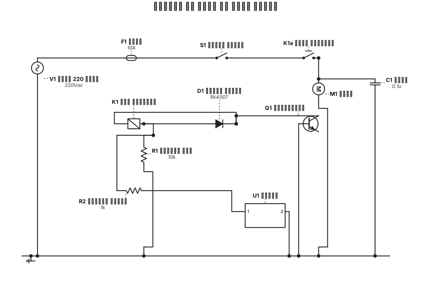
التحكم في محرك عن طريق relais
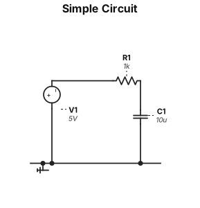
A simple circuit
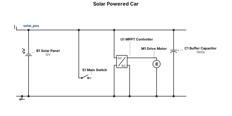
I want to make a car which runs with just solar power
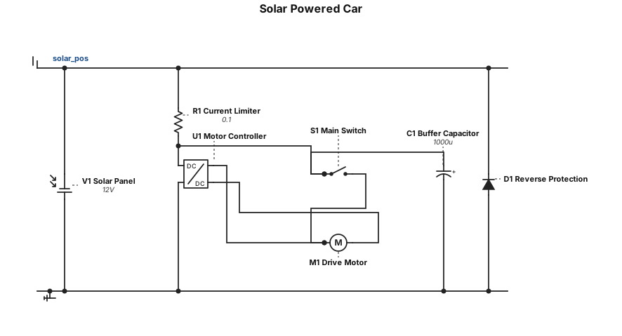
I want to build a car which just need solar energy to run
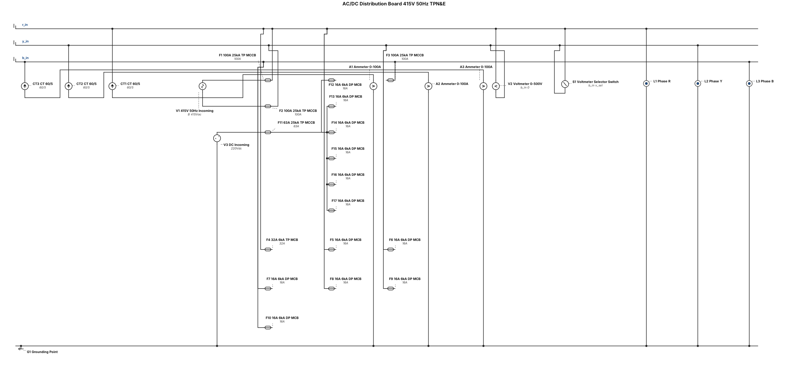
Supply, lnstallation. Testing & Commissioning of Sheet steel clad (16 SWG), dust and vermin proof, free standing, floor mounting, AC/DC Distribution Board, 415V, 50H2, lndoor type, complete with all wirlrg prcvislons for bottom / top entry, grounding polnts,3 -point locking system with 1004 hard drawn electrolytic copper Bus-bars TPN&E, painted with electro coated and wet (electrostatic) epoxy resin powder coated paint in an automatic painting & drving chamber ln accordance with IEC 298, tne AC/DC Distr"ibution Board is manufactured, assernbled & tested by comprising the following components : INCOMING: 1 No. 1004, 25KA, TP MCCB with Adjustable thermal Over"load & adjustable magnetic short circuit releases 3 Nos. Current Transformer, Ratio: 60/5wlth suttable accuracy & Brand & Origin :Taiwan, Taiwan 3 Nos Ammeter, 0-1004, 1 No. Voltmeter 0-500V with Selector switch , (Secure, lndia) 3 No. Phase indlcation Lamp,( OUTGOING: 01, No" 32A,6KA, TP MCB with Protection & Controiof the circuits against Overloads & Short-clrcuits. 06 Nos. 164, 6KA, DP MCB with Protection & Control of the ciicurts agai nst Overloads & Short-circuits. DC PANEL INCOMING: l- No. 63A, 25KA, TP MCCB wrth Adiustable thermal Overioad & adjustabie magnetic short circuit re eases OUTGOING: 06 Nos. 16A,6KA, DP MCB with Protection & Controlof the circuits against Overloads & Short-circuits. Create a controlling Diagram
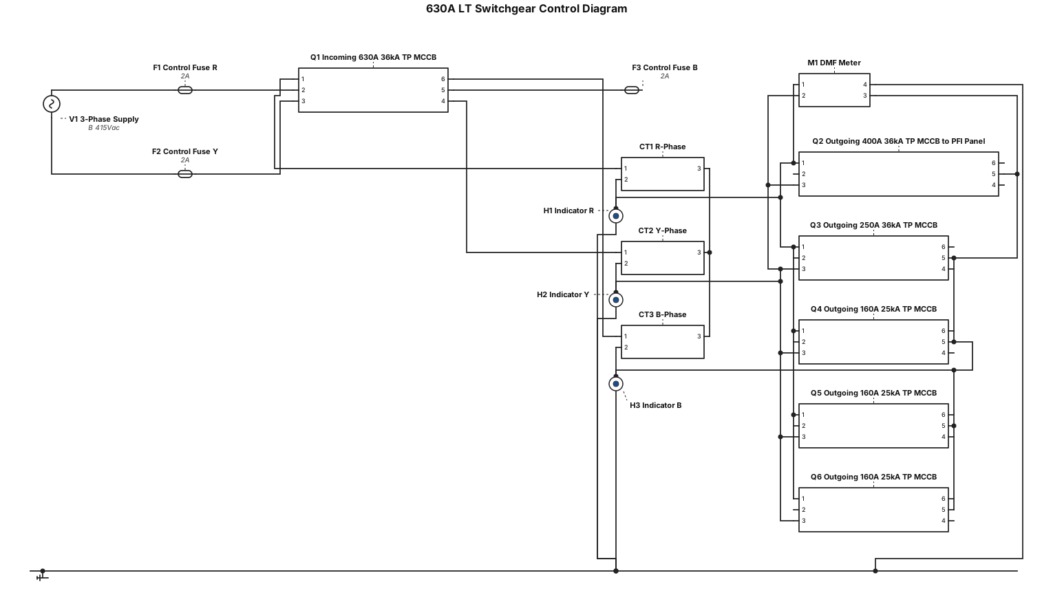
A 630 A LT Switchgear, Incoming 630A, 36KA, TP MCCB with 3 nos. CT-ratio 600/5A, 1 nos. DMF meter, 3 nos. Indicator Lamp, 1 set Control Fuse, Outgoing 400A, 36KA, TP MCCB for PFI Panel,1 nos. 250A, 36KA, TP MCCB, 3 nos. 160A, 25KA, TP MCCB. Now Create a control Diagram
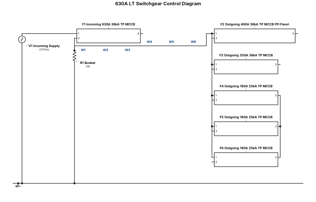
A 630 A LT Switchgear, Incoming 630A, 36KA, TP MCCB, Outgoing 400A, 36KA, TP MCCB for PFI Panel,1 nos. 250A, 36KA, TP MCCB, 3 nos. 160A, 25KA, TP MCCB. Now Create a control Diagram
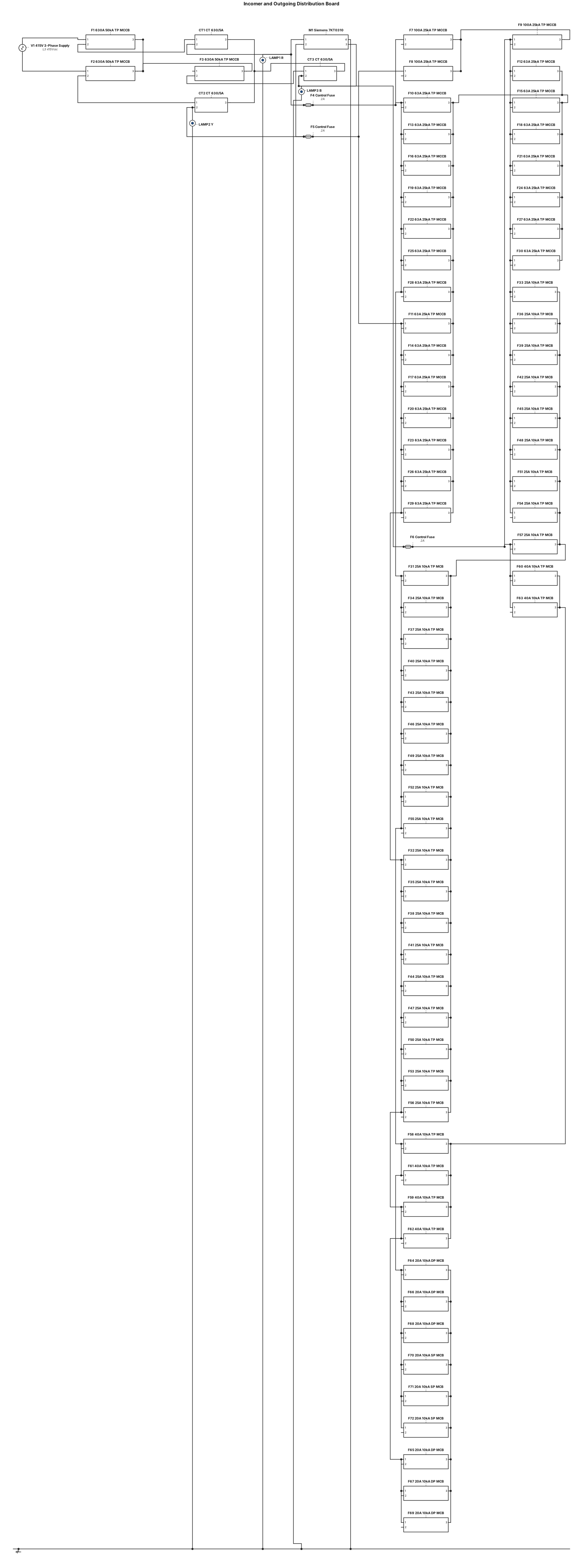
INCOMING 01 Nos. 630 A, 50KA, TP MCCB with Adjustable thermal overload and adjustable magnetic short-circuit release. 3 Nos. Current Transformer, ratio: 630/5A with suitable accuracy and burden 1 No. Digital Multifunction Meter (Siemens 7KT0310, India) 3 Nos. Phase Indication Lamp (R+Y+B) 1 Set of Control fuse OUTGOING: 01 Nos. 100 A, 25KA, TP MCCB with Adjustable thermal overload and adjustable magnetic short-circuit release. 07 Nos. 63 A, 25KA, TP MCCB with Adjustable thermal overload and adjustable magnetic short-circuit release. 09 Nos. 25A TP, 10KA, MCB with Protection & Control of the circuits against Overloads & Short-circuits. 02 Nos. 40 A TP, 10KA, MCB with Protection & Control of the circuits against Overloads & Short-circuits. 03 Nos. 20 A DP, 10KA, MCB with Protection & Control of the circuits against Overloads & Short-circuits. 03 Nos. 20 A SP, 10KA, MCB with Protection & Control of the circuits against Overloads & Short-circuits.
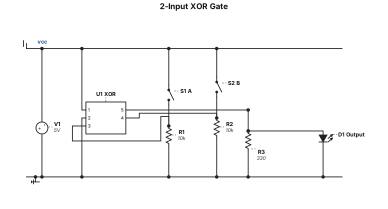
using tinker cad imlement a 2 input xor gate applu a, b=00,01,10,11 observe output and prepare the truth table
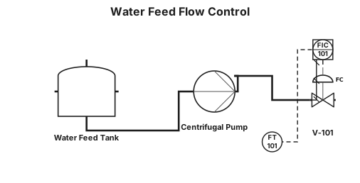
A water feed tank, centrifugal pump, control valve, and outlet line with a flow transmitter sending an electrical signal to a control-room flow controller that pneumatically controls the valve.
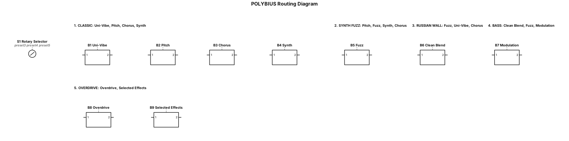
Update the POLYBIUS routing diagram. Keep the existing blocks and layout. Add five numbered routing presets beside the five-position rotary selector: 1. CLASSIC: Uni-Vibe, Pitch, Chorus, Synth 2. SYNTH FUZZ: Pitch, Fuzz, Synth, Chorus 3. RUSSIAN WALL: Fuzz, Uni-Vibe, Chorus 4. BASS: Clean Blend, Fuzz, Modulation 5. OVERDRIVE: Overdrive, Selected Effects Show these as selectable presets controlled by the rotary selector. Do not draw five separate complete audio circuits. Keep the diagram simple and readable. Use labeled blocks and arrows only.
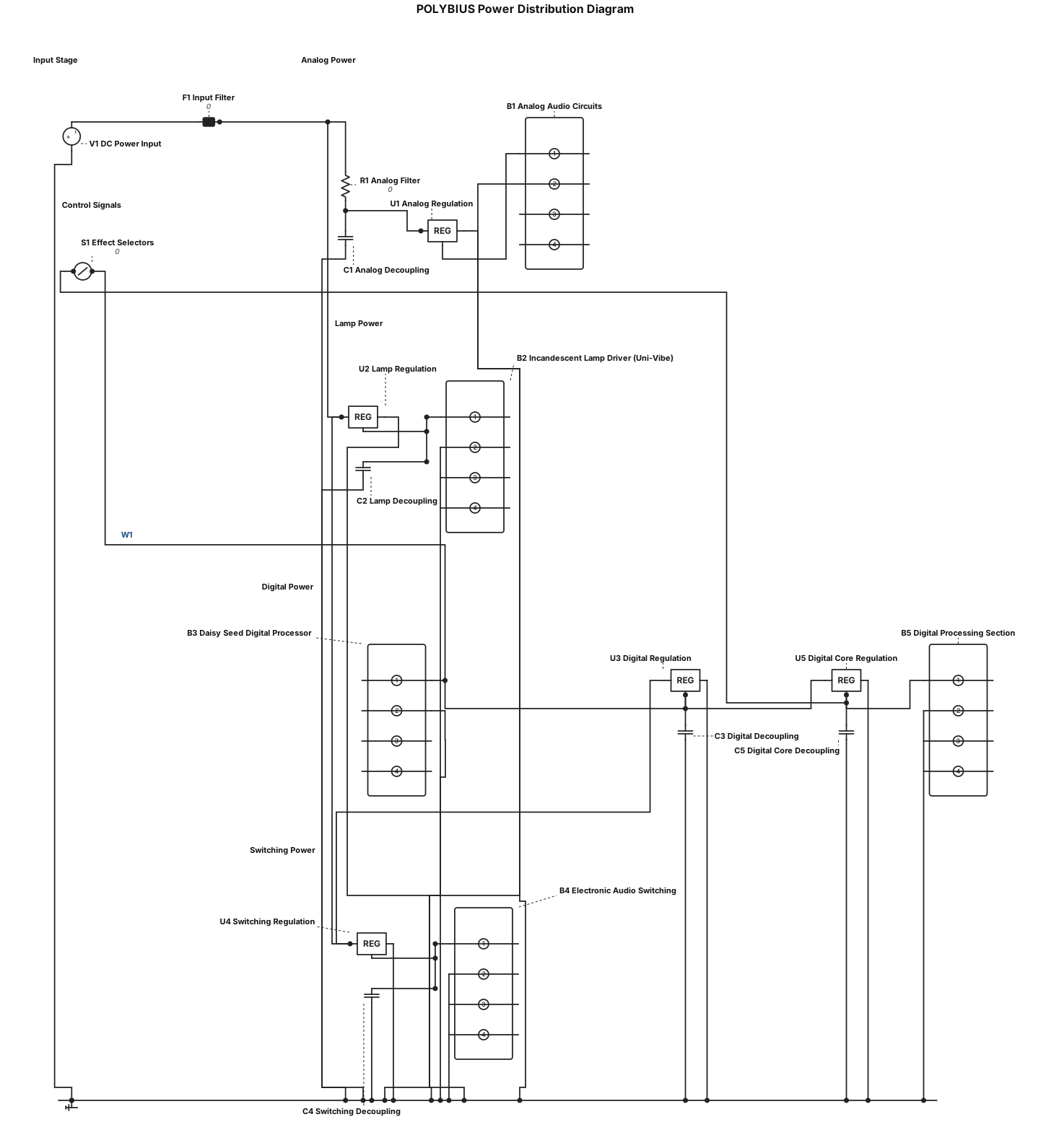
Draw a simple power distribution block diagram for a guitar and bass effects pedal called POLYBIUS. Show one DC power input feeding four separately labeled power sections: 1. Analog audio circuits 2. Incandescent lamp driver for the Uni-Vibe 3. Daisy Seed digital processor 4. Electronic audio switching Show filtering and regulation blocks where needed. Keep the lamp-driver power separate from sensitive analog audio power. Show the Daisy Seed powering its digital processing section and receiving control signals from the effect selectors. Do not specify voltage values, current ratings, or component numbers. Use simple rectangles and arrows only. Keep power connections separate from audio signal connections. Do not draw a detailed circuit schematic. Title: POLYBIUS Power Distribution Diagram.
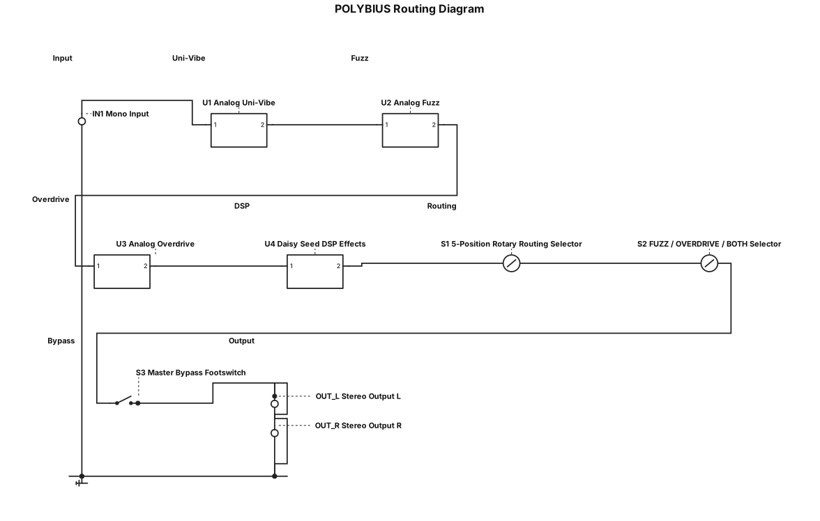
Draw a simple block diagram for a guitar effects pedal called POLYBIUS. Show a mono input, analog Uni-Vibe, analog fuzz, analog overdrive, Daisy Seed DSP effects, a five-position rotary routing selector, a FUZZ / OVERDRIVE / BOTH selector, one master bypass footswitch, and stereo outputs. Use arrows to show signal flow. Use labeled rectangles only. Keep the drawing simple and uncluttered. Title it “POLYBIUS Routing Diagram.”
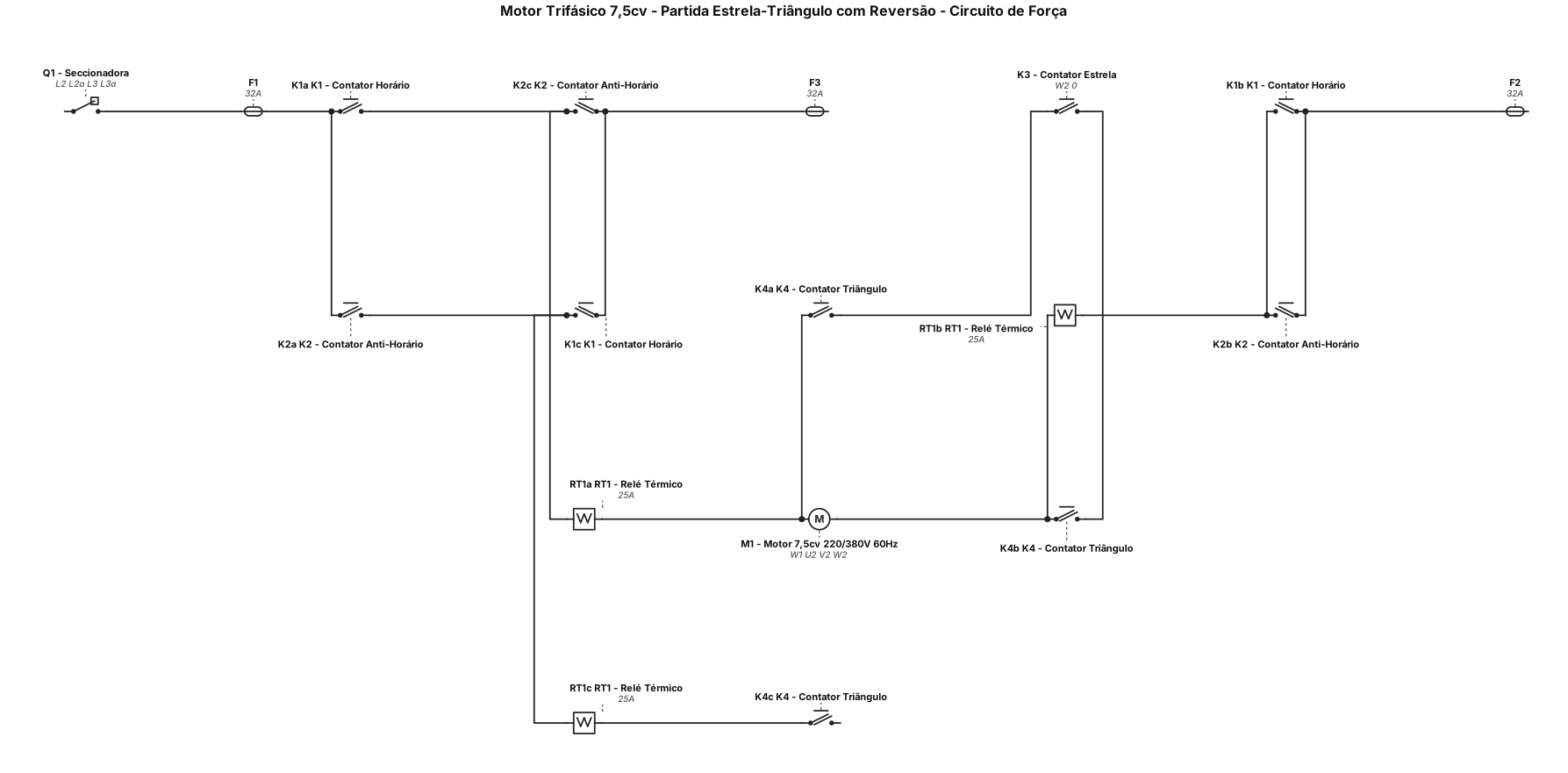
Analise a foto da atividade do professor e desenvolva o projeto elétrico completo, seguindo todos os requisitos apresentados. Quero dois esquemas técnicos, visualmente semelhantes aos feitos no CADe SIMU, com simbologia elétrica industrial IEC, fundo branco, linhas nítidas, componentes identificados e conexões organizadas. 1. CIRCUITO DE FORÇA: motor trifásico de 7,5 cv, 220/380 V, 60 Hz, partida estrela-triângulo e reversão horária/anti-horária. Inclua alimentação L1, L2 e L3, proteções, contatores de reversão K1 e K2, relé térmico RT, contatores estrela K3 e triângulo K4 e motor M1 com seis terminais U1, V1, W1, U2, V2 e W2. Desenhe todas as ligações de potência corretamente, incluindo a inversão de duas fases. 2. CIRCUITO DE COMANDO: diagrama ladder completo com S0 (parada NF), S1 (partida horária NA), S2 (partida anti-horária NA), bobinas e contatos auxiliares K1, K2, K3 e K4, temporizador KT, contato NF 95–96 do relé térmico, contatos de selo e intertravamentos elétricos. A temporização deve desligar estrela antes de ligar triângulo, sem sobreposição. Impeça acionamentos simultâneos incompatíveis e reversão direta com o motor funcionando. Inclua legenda, identificação dos terminais, cálculos possíveis, explicação do funcionamento e critérios de dimensionamento. Não invente dados ausentes. Confira a compatibilidade entre a tensão da rede e a ligação do motor. Entregue os dois esquemas em alta resolução e um PDF técnico organizado, além do arquivo editável nativo, se suportado. Quero um resultado completo, legível e tecnicamente coerente, semelhante a um projeto profissional do CADe SIMU, não um desenho ilustrativo. Revise todas as conexões e informe qualquer parte que não tenha sido validada. Não afirme que o arquivo é nativo do CADe SIMU se não for.
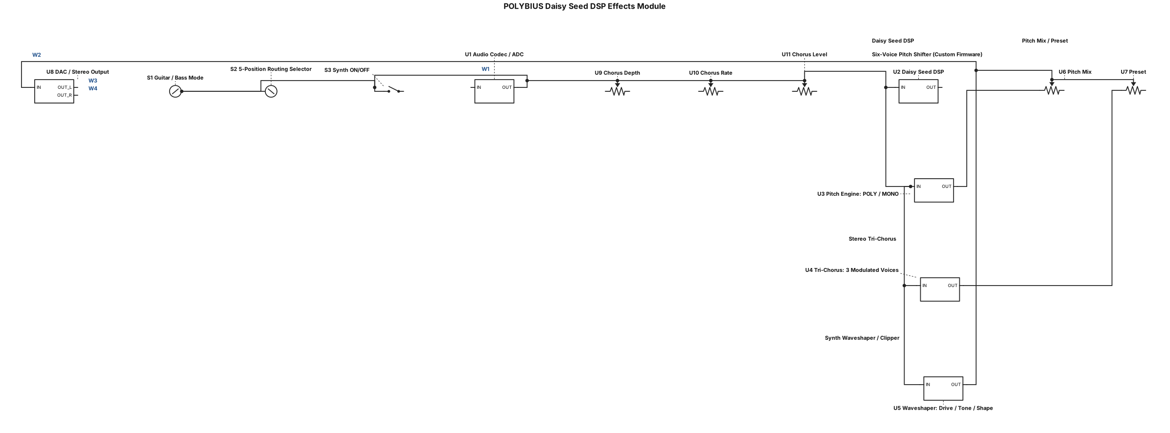
Draw a functional circuit block diagram for the digital effects module of a guitar/bass effects pedal called POLYBIUS, built around a Daisy Seed digital signal processing platform. Show a mono analog audio input entering an appropriate audio codec/interface and analog-to-digital conversion stage, followed by DSP processing, digital-to-analog conversion, and stereo output connections. Inside the DSP block, show three separate effects: (1) a six-voice pitch-shifting engine with POLY mode for chords and MONO mode for dominant-note tracking, (2) a stereo tri-chorus with three independently modulated delay voices, and (3) a synth-style waveshaping and clipping engine with adjustable Drive, Tone, and Shape controls. Include Pitch Mix and Preset controls, a Chorus Depth, Rate, and Level control group, and a Synth ON/OFF control. Show Guitar/Bass mode selection and a control interface for the external five-position routing selector. Clearly label the six-voice pitch shifter as custom firmware that must be developed and tested, not a built-in guaranteed feature. Use simple, readable functional blocks, not a detailed component schematic. Title it “POLYBIUS Daisy Seed DSP Effects Module.”
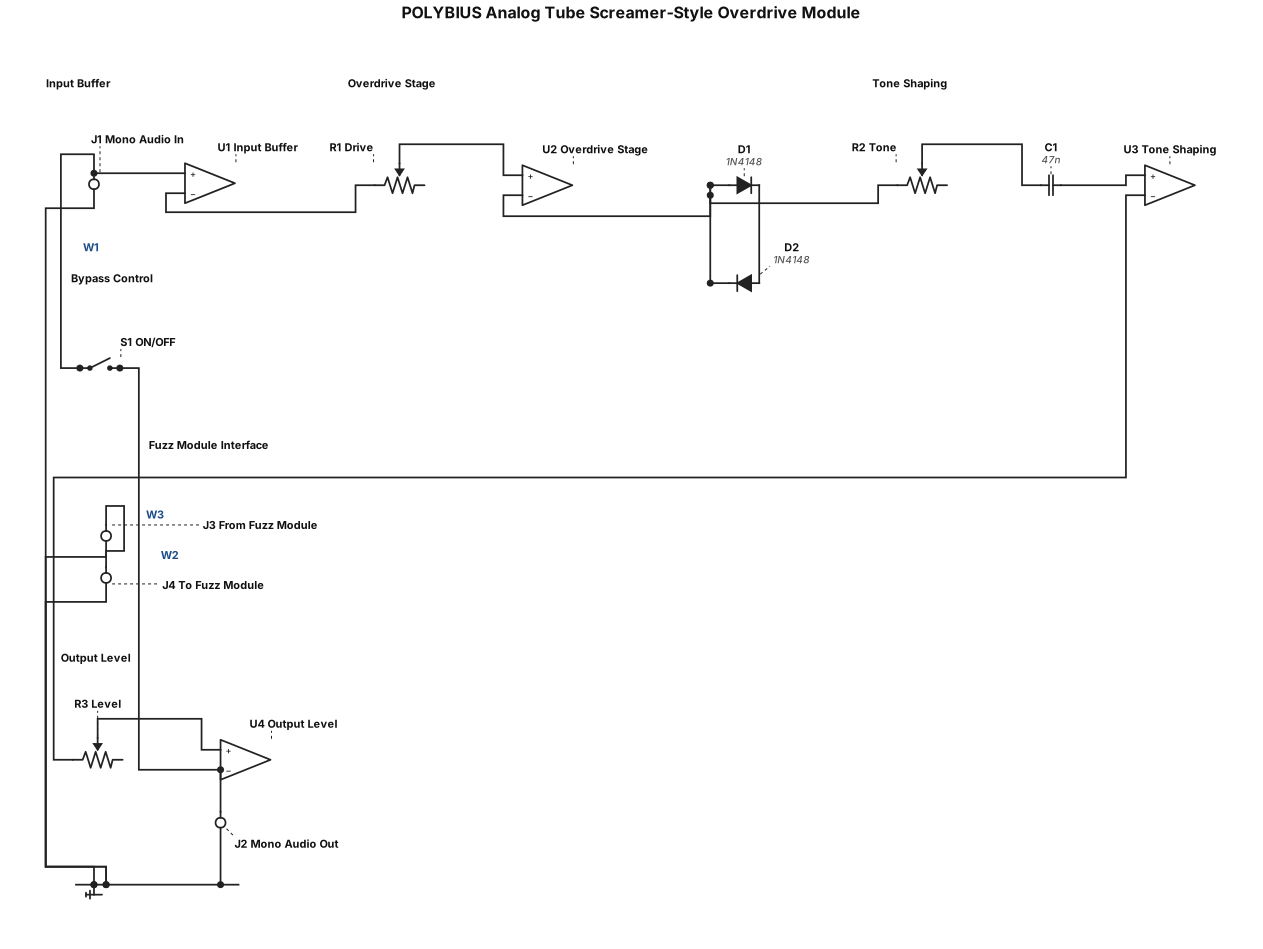
Draw a functional circuit block diagram for the analog overdrive module of a guitar/bass effects pedal called POLYBIUS. Show a mono input buffer, an op-amp-based overdrive stage with diode clipping in its feedback path, a tone-shaping stage, and an output Level stage. Include Drive, Tone, and Level controls, an ON/OFF control, and mono audio input/output connections. Keep this module separate from the analog fuzz module, but show clearly labeled connections that allow the two modules to be connected in series when selected by the main routing system. Make the design suitable for both guitar and bass, with enough low-frequency response to avoid unintentionally removing the bass fundamental. Use simple, readable functional blocks, not a detailed component schematic. Title it “POLYBIUS Analog Tube Screamer-Style Overdrive Module.”
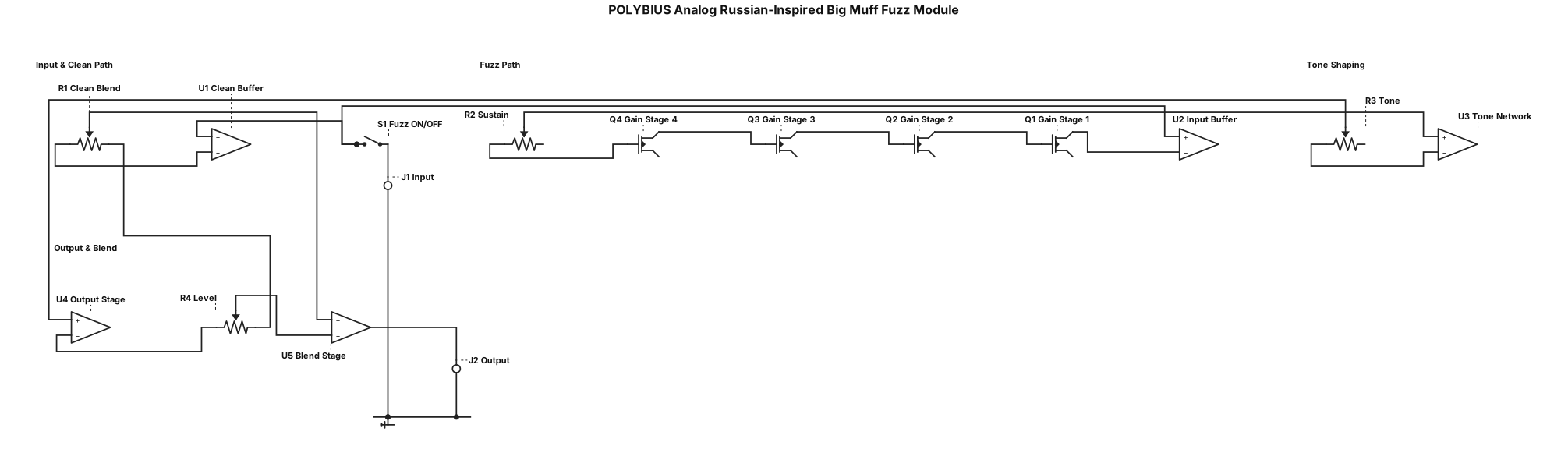
Draw a functional circuit block diagram for the analog fuzz module of a guitar/bass effects pedal called POLYBIUS. Base the design on the general Green Russian / Sovtek Civil War-inspired Big Muff topology, without claiming an exact vintage clone. Show a mono input buffer, multiple transistor-based gain and clipping stages, a passive tone-shaping network, and an output stage. Include Sustain, Tone, and Level controls, plus a Clean Blend control that mixes the original clean signal with the fuzz signal to preserve bass definition. Show the clean signal and fuzz signal paths separately until they reach the blend stage. Include a fuzz ON/OFF control and mono audio input/output connections. Design the functional architecture to retain low bass frequencies, including the fundamental of a five-string bass’s low B string. Use simple, readable functional blocks, not a detailed component schematic. Title it “POLYBIUS Analog Russian-Inspired Big Muff Fuzz Module.”
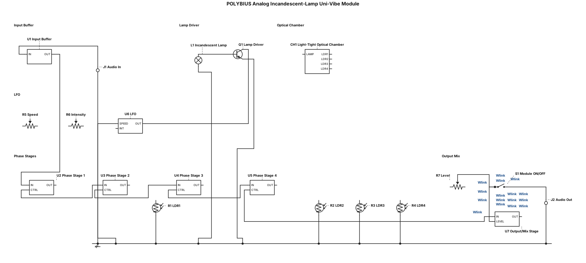
Draw a functional circuit block diagram for the analog Uni-Vibe module of a guitar/bass effects pedal called POLYBIUS. Show a mono audio input buffer feeding four cascaded phase-shifting stages controlled by four light-dependent resistors (LDRs). Show a real incandescent lamp inside a light-tight optical chamber illuminating all four LDRs. Include an analog low-frequency oscillator (LFO), a transistor-based lamp driver, Speed and Intensity controls, and an output/mix stage with a Level control. The lamp driver must power the incandescent bulb; do not connect the bulb directly to the LFO. Show the audio path and lamp-control path separately with labeled arrows. Include a module ON/OFF control and mono audio input/output connections. Use simple, readable functional blocks, not a detailed component schematic. Do not substitute an LED for the incandescent lamp. Title it “POLYBIUS Analog Incandescent-Lamp Uni-Vibe Module.”
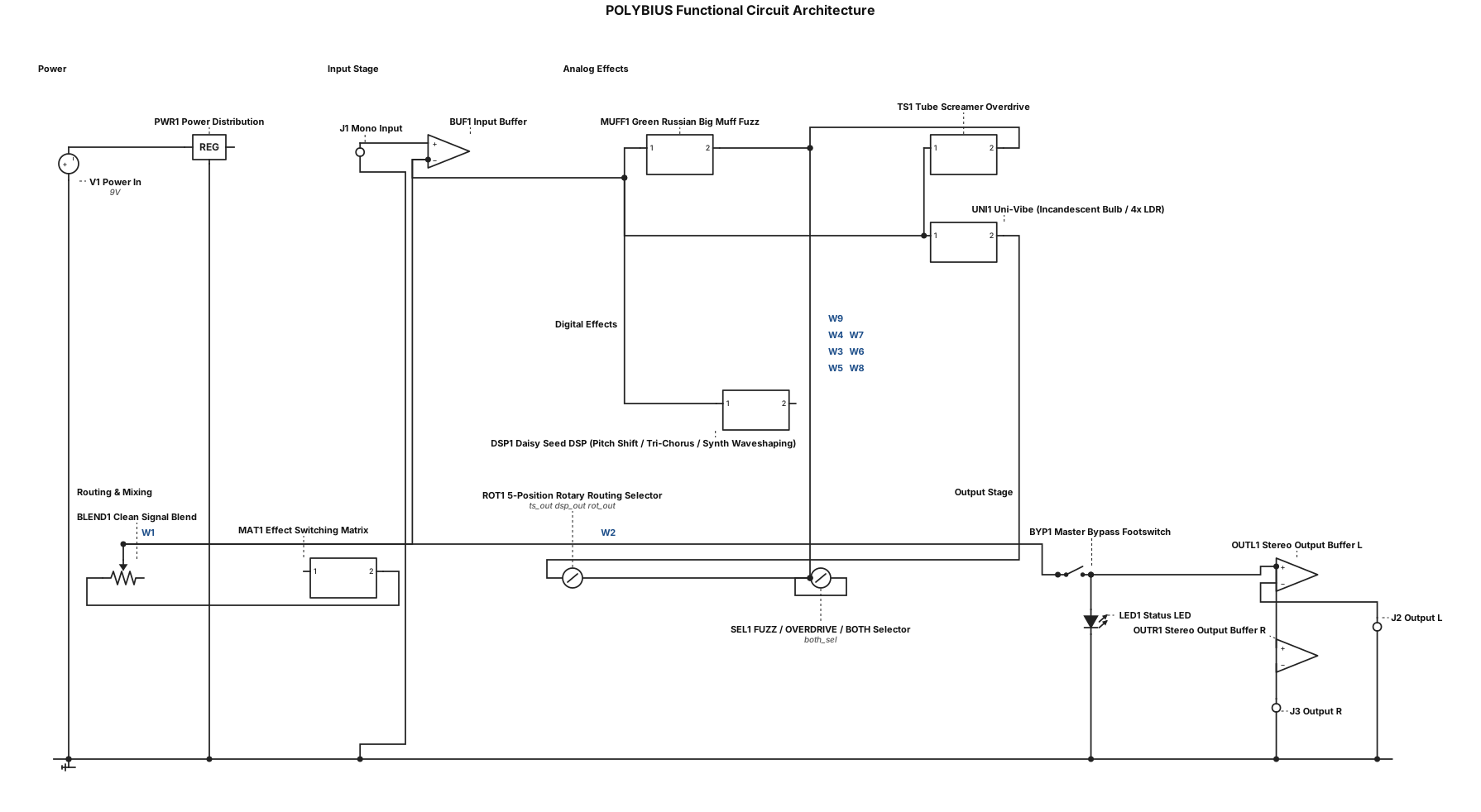
Draw a functional block diagram for a guitar/bass effects pedal called POLYBIUS. Show a mono input buffer branching to four modules: analog incandescent-bulb/four-LDR Uni-Vibe, analog Green Russian-inspired Big Muff fuzz, analog Tube Screamer-style overdrive, and Daisy Seed DSP containing pitch shifting, tri-chorus, and synth waveshaping. Connect these modules through a five-position rotary routing selector and an effect-switching matrix. Add a clean-signal blend, stereo output buffers, one master bypass footswitch, status LED, and separate power distribution. Include a three-position FUZZ / OVERDRIVE / BOTH selector. Label all blocks and show signal direction with arrows. Use simple, readable functional blocks, not a detailed component schematic. Title it “POLYBIUS Functional Circuit Architecture.”
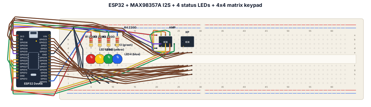
esp32 connected to a max98357A i2s audio amplifier and 4 status leds. 4x4 matrix push buttons connected to the pins on the left side of the esp32