
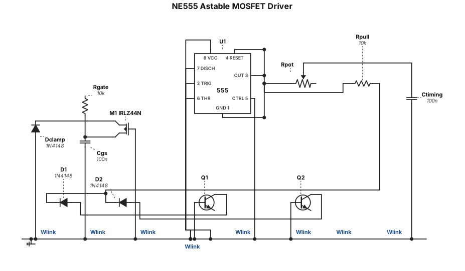
Schematic: NE555 timer in astable mode. Pin 8 to 5V, pin 1 to GND. Pins 2+6 tied to 47k pot to 5V and 100nF to GND. Pin 7 to same node. Pin 3 through 10k to IRLZ44N MOSFET gate. Pin 4 pulled to 5V through 10k, with two 1N4148 diodes (cathodes at pin 4) from two NPN transistor collectors. MOSFET drain to "IGT IN", source to "IGT OUT" and GND. 1N4148 clamp across MOSFET. 100nF gate to source.
ENGINEERING DRAWING ARCHIVE · REAL SPECS
Engineering Diagram Examples from Real Specifications
Browse eligible circuit, ladder, single-line, P&ID, breadboard, timing, and logic drawings with their original prompts.
Browse 553 real creationsCOMMUNITY OUTPUTS · EXACT PROMPTS
All visitor creations
Showing 529–552 of 553. No stock examples or system defaults. Choose a tool, study a real result, then reopen its prompt as your starting point.
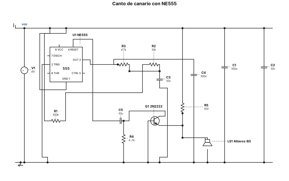
Diseña un esquema electrónico con un circuito integrado NE555 alimentado a 9 V para imitar el canto de un canario, con trinos rápidos, variación de frecuencia y sonido natural. Numera todos los pines del NE555, indica los valores de resistencias y condensadores, dibuja todas las conexiones y añade una etapa de salida para un altavoz. Utiliza símbolos electrónicos normalizados.
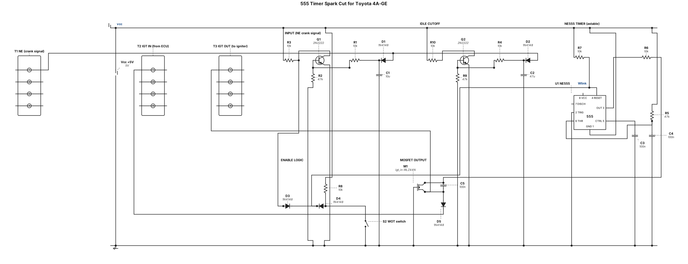
Draw a schematic for a 555 timer spark cut circuit for a Toyota 4A-GE engine. The circuit has these sections: 1. INPUT: A pulse source labeled "NE (crank signal)" feeding into a 1N4148 diode (D1), then into a node. From that node: a 10uF capacitor (C1) to ground, a 10k resistor (R1) to the base of an NPN transistor Q1 (2N2222), and a 47k potentiometer (R2) from base to ground. Q1 emitter to ground, collector through a 10k resistor (R3) to +5V. 2. Same as section 1 but with a 47uF capacitor (C2) and a second NPN Q2 (2N2222), labeled "IDLE CUTOFF". 3. NE555 TIMER in astable mode: Pin 8 to +5V, Pin 1 to GND, Pin 5 with 100nF cap to GND. Pins 2 and 6 tied together, connected to a 47k potentiometer (R5) to +5V, and a 100nF capacitor (C3) to ground. Pin 7 connected to the junction of R5 and pin 2/6. Pin 3 (output) through a 10k resistor (R6) to the gate of an N-channel MOSFET M1 (IRLZ44N). Pin 4 (enable) pulled to +5V through a 10k resistor (R7). 4. ENABLE LOGIC: A 1N4148 diode (D3) from Q1 collector to 555 pin 4. A 1N4148 diode (D4) from a "WOT switch" node to 555 pin 4. The WOT switch node is pulled to +5V through a 10k resistor (R8), and the switch connects to ground (closes when throttle is not wide open). 5. MOSFET (M1, IRLZ44N): Gate from R6, Drain connected to "IGT IN (from ECU)" label, Source connected to "IGT OUT (to igniter)" label. A 1N4148 diode (D5) from Drain to Source (cathode at drain). A 100nF capacitor from Gate to Source. Label all components with reference designators and values. Use standard IEEE schematic symbols.
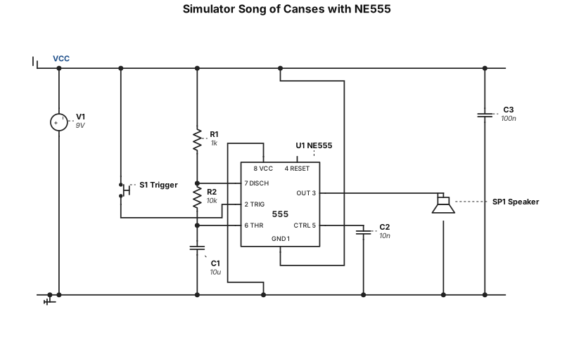
Simulator song of canses with ne555
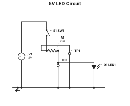
A 5 V LED circuit with a 220 ohm series resistor, an SPST switch, and labeled test points before and after the resistor.
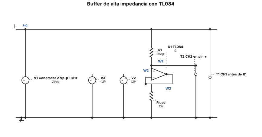
Propósito: Actuar como etapa de aislamiento con alta impedancia de entrada, evitando que el sensor de medición se "cargue" y pierda voltaje. • Esquema: Salida conectada directamente al pin inversor (-). Vin directo al pin (+). • Fórmula: Vout = Vin • Actividad de Impedancia: Conecta la señal del generador (2 Vp-p, 1 kHz) al buffer a través de una resistencia en serie de 1 MΩ. Mide con CH1 *antes* de la resistencia y con CH2 *después* (en el pin +). • Observación esperada: A pesar de la enorme resistencia de 1 MΩ, el voltaje no cae, demostrando que el TL084 no consume corriente significativa (gracias al JFET). Evita limitar la práctica a solo ver que la salida copia la entrada.
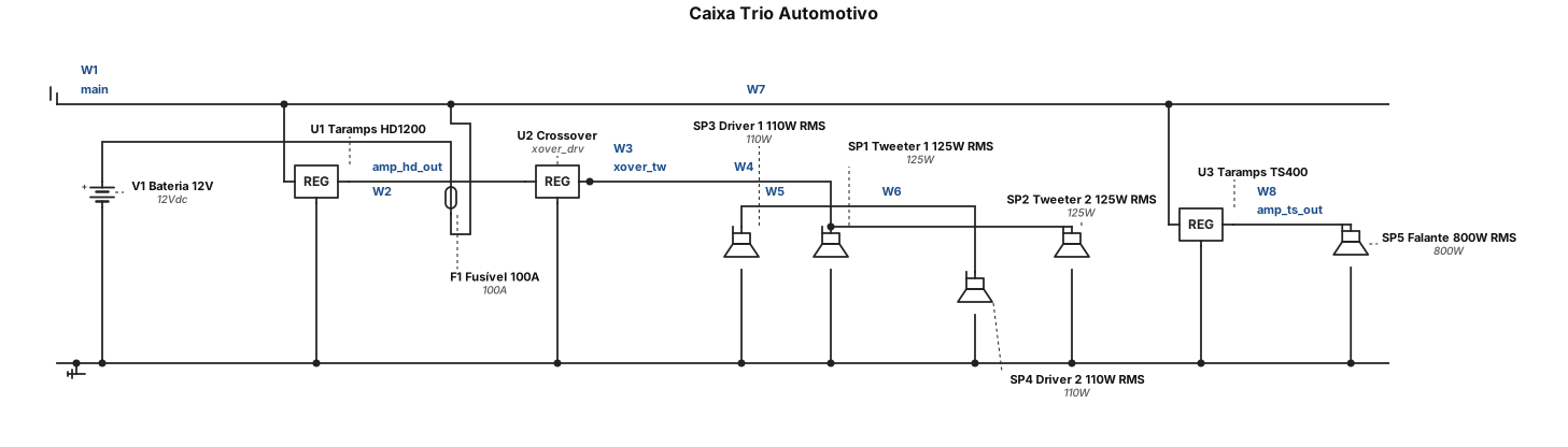
uma caixa trio de som automotivo com 2 tweeter de 125rms e 2 driver com 110 rms mais modulo taramps hd1200 mais crossover mais modulo ts400 e um falante de 800rms
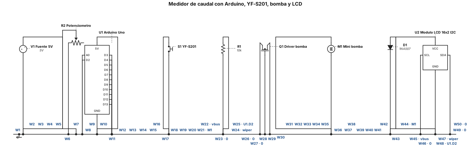
haz el diseño y coneexcion de circuito con arduino, yf-s201. mini bomba, lcd con su modulo. es un medidor de caudal pero haora queremos hacerlo con un potenciometro para ajustar su potencia
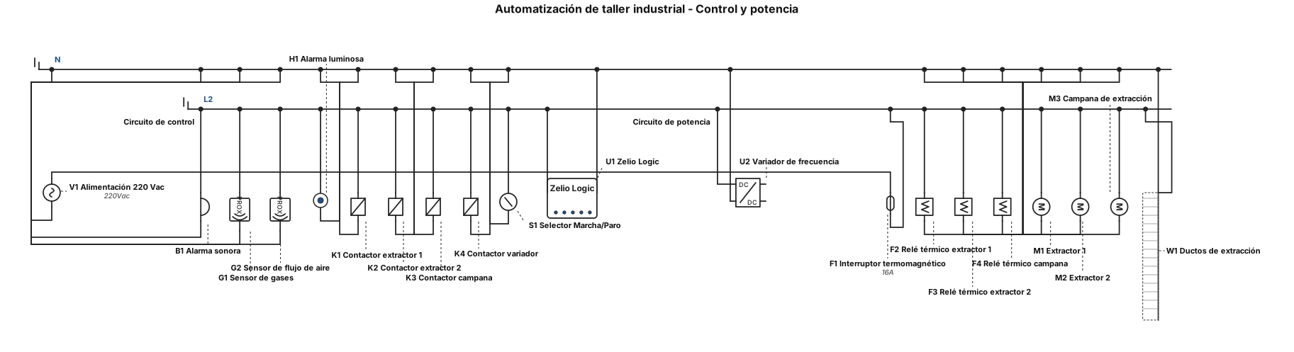
Crea un diagrama de automatización para un taller industrial. Incluye un relé Zelio Logic, un sensor de gases, un sensor de flujo de aire, dos extractores, una campana de extracción, ductos, un variador de frecuencia, contactores, relés térmicos, un interruptor termomagnético y una alarma luminosa y sonora. Muestra el circuito de control y el circuito de potencia por separado. El Zelio debe controlar los extractores y activar la alarma cuando se detecte una condición anormal. Utiliza símbolos eléctricos industriales y etiquetas en español. Presenta el diagrama de forma clara y ordenada.
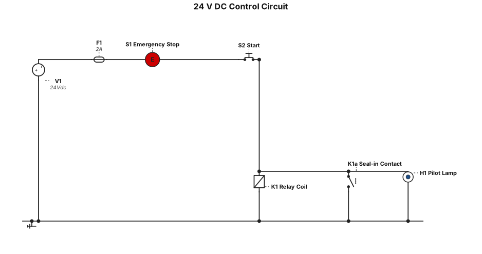
A 24 V DC control circuit with a fuse, emergency stop, start pushbutton, relay coil, seal-in contact, and one pilot lamp that turns on with the relay.
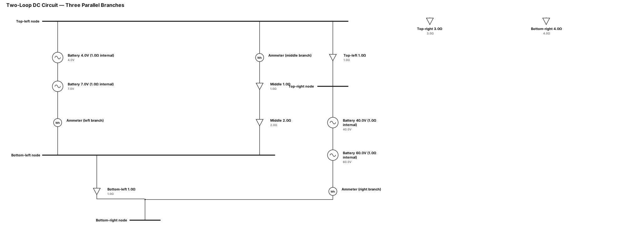
"A single-line diagram of a two-loop DC circuit with three parallel vertical branches (left, middle, right) connected by top and bottom horizontal wires. Left branch contains a 4.0V battery (1.0Ω internal resistance), a 7.0V battery (1.0Ω internal resistance), and an ammeter. Top-left horizontal wire has a 1.0Ω resistor. Bottom-left horizontal wire has a 1.0Ω resistor. Middle branch contains an ammeter, a 1.0Ω resistor, and a 2.0Ω resistor. Right branch contains a 40.0V battery (1.0Ω internal resistance), a 60.0V battery (1.0Ω internal resistance), and an ammeter. Top-right horizontal wire has a 3.0Ω resistor. Bottom-right horizontal wire has a 4.0Ω resistor. All components are connected in series within their respective branches."
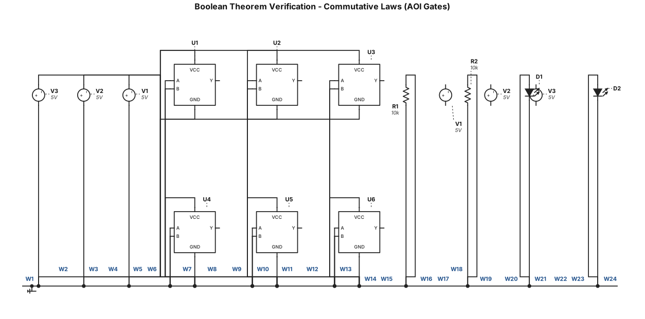
Verify Boolean theorems using AOI gates: commutative laws
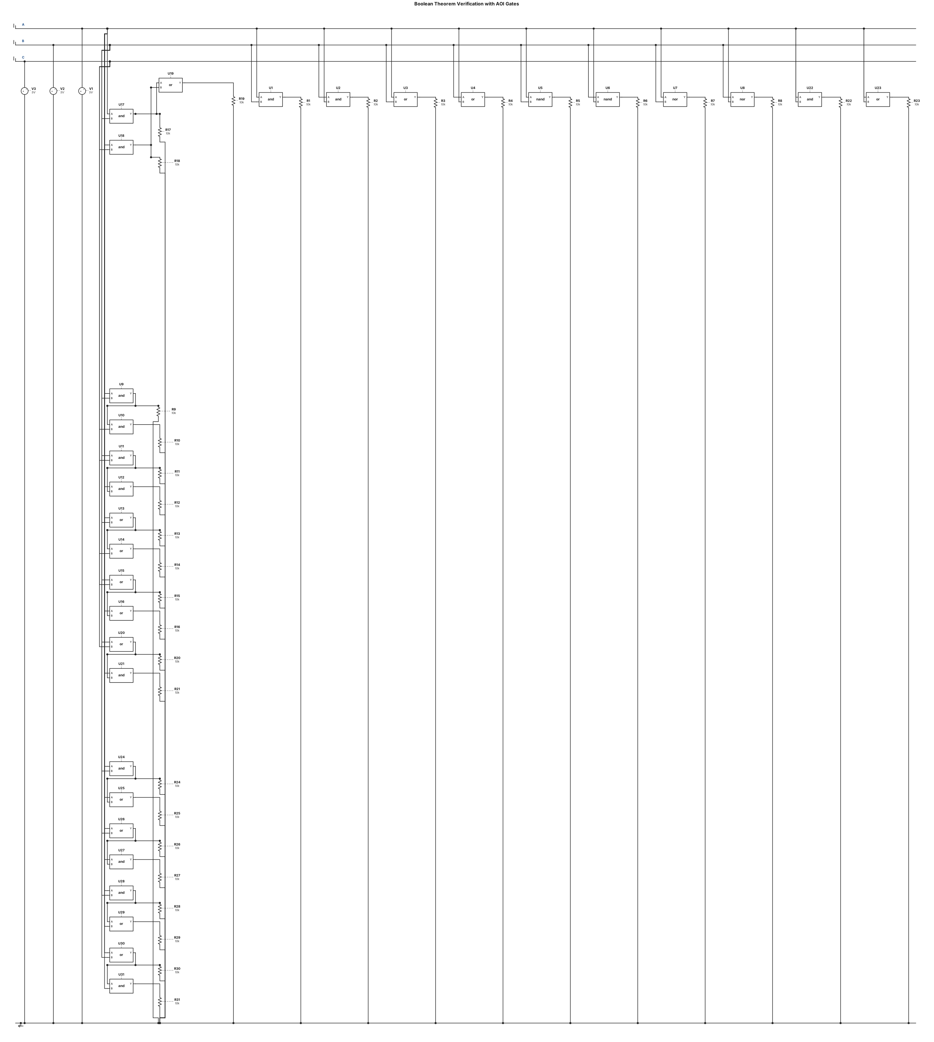
Verify Boolean theorems using AOI gates: commutative, associative, distributive, absorption and idempotent laws
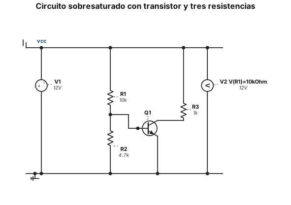
Diseña un circuito que cumpla las siguientes características: debe tener al menos tres resistencias, una de ellas debe valer 10kOhm y las otras dos no deben exceder dicho valor, y al menos un transistor. El circuito debe estar sobresaturado, es decir, tener cos(phi)>1. Adjunta una captura del circuito diseñado donde se muestre adicionalmente cuánto vale el voltaje de la resistencia de 10 kOhm, e indica qué IA has empleado para diseñar el circuito
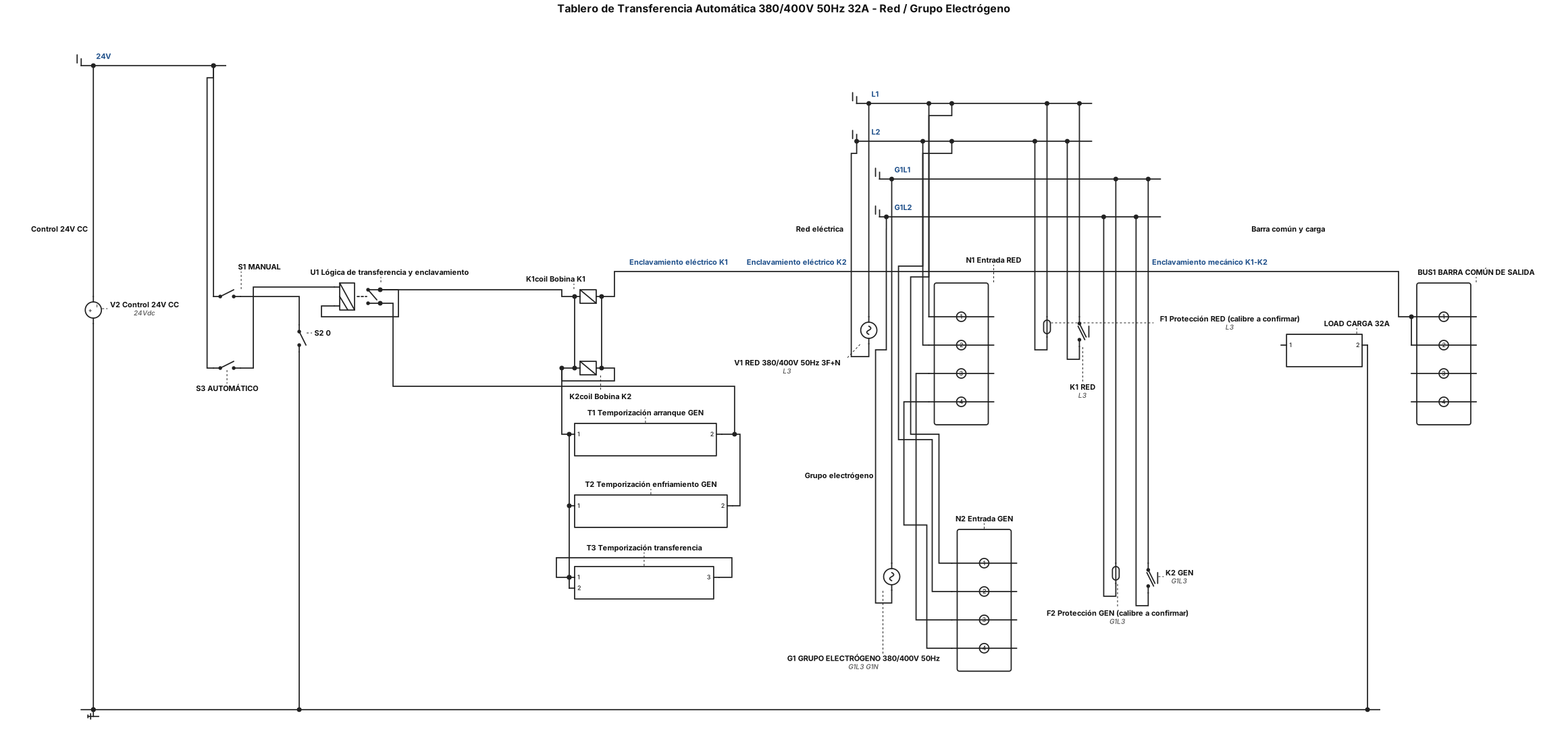
Diseñar un diagrama unifilar de un tablero de transferencia automática entre red eléctrica trifásica de 380/400 V, 50 Hz, 32 A y un grupo electrógeno. Incluir dos fuentes de alimentación, protecciones independientes, dos contactores K1 y K2 con enclavamiento mecánico y eléctrico, una barra de salida común y una carga. Agregar un sistema de control de 24 V CC con tres modos: MANUAL, 0 y AUTOMÁTICO. En automático, si falla la red, arrancar el generador, comprobar que su tensión sea estable y transferir la carga. Cuando vuelva la red, retornar la carga a la red y detener el generador después de un tiempo de enfriamiento. Mostrar los componentes identificados y las conexiones de forma clara. No inventar modelos ni calibres de protecciones que no estén confirmados. Es un proyecto educativo que requiere revisión técnica antes de conectar tensión real.
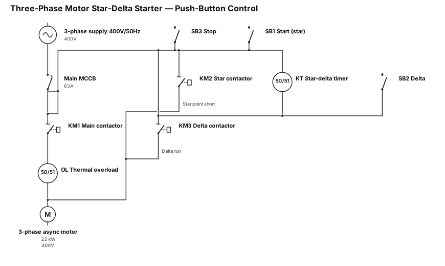
Draw and explain the operating principle of a circuit for starting a three-phase asynchronous motor using the star-delta (Y-Δ) connection method, controlled via push-buttons (one button for star-connection operation, one for delta-connection operation, and one for stopping the motor).
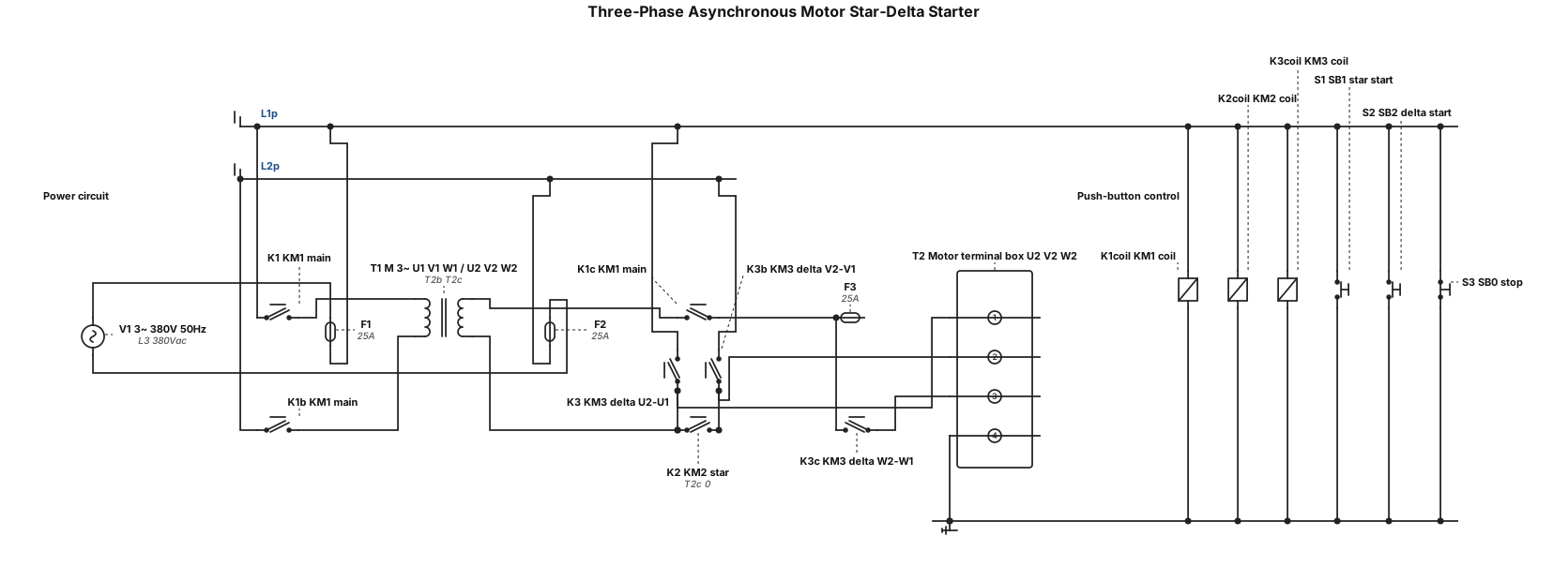
Draw and explain the operating principle of a circuit for starting a three-phase asynchronous motor using the star-delta (Y-Δ) connection method, controlled via push-buttons (one button for star-connection operation, one for delta-connection operation, and one for stopping the motor).
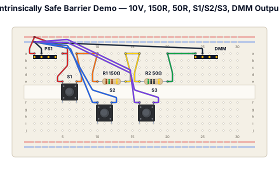
Create a beginner-friendly breadboard circuit based on an intrinsically safe barrier demonstration. Use a 10 V DC power supply, one 150 Ω resistor, one 50 Ω resistor, and three normally-open momentary push buttons. Do not use Arduino or any microcontroller. Show the exact breadboard hole connections, power rails, jumper wires, resistor positions, and multimeter probe positions. Label every component and connection clearly. Arrange the circuit as follows: push button S1 in series with the supply input, followed by the 150 Ω resistor and then the 50 Ω resistor. Connect push button S2 from the junction between the two resistors to the negative rail. Connect push button S3 from the output after the 50 Ω resistor to the negative rail. Connect the power supply negative terminal to the negative rail. Show how to measure output voltage using the multimeter. Generate an actual breadboard layout, not only a circuit schematic. Explain how the circuit behaves when each button is pressed. Flag any floating output or excessive current risks and recommend safe low-current test conditions.
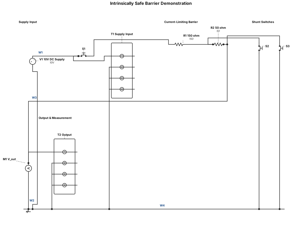
Create a beginner-friendly breadboard circuit based on an intrinsically safe barrier demonstration. Use a 10 V DC power supply, one 150 Ω resistor, one 50 Ω resistor, and three normally-open momentary push buttons. Do not use Arduino or any microcontroller. Show the exact breadboard hole connections, power rails, jumper wires, resistor positions, and multimeter probe positions. Label every component and connection clearly. Arrange the circuit as follows: push button S1 in series with the supply input, followed by the 150 Ω resistor and then the 50 Ω resistor. Connect push button S2 from the junction between the two resistors to the negative rail. Connect push button S3 from the output after the 50 Ω resistor to the negative rail. Connect the power supply negative terminal to the negative rail. Show how to measure output voltage using the multimeter. Generate an actual breadboard layout, not only a circuit schematic. Explain how the circuit behaves when each button is pressed. Flag any floating output or excessive current risks and recommend safe low-current test conditions
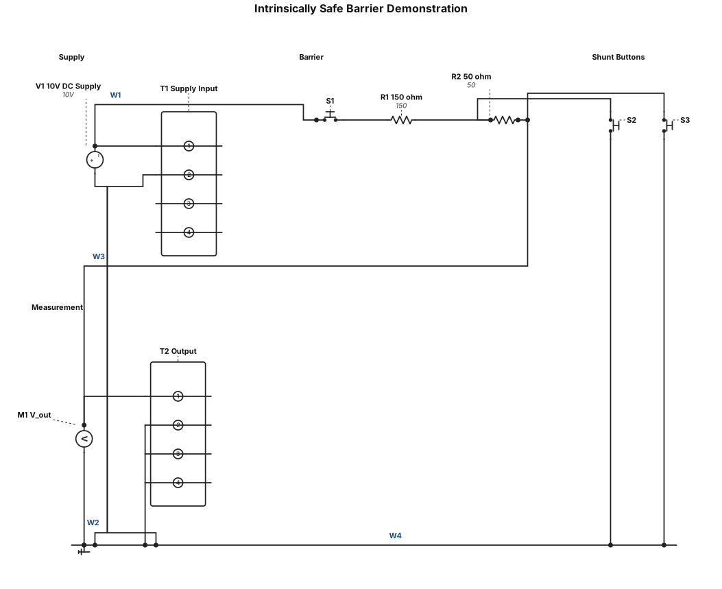
Create a beginner-friendly breadboard circuit based on an intrinsically safe barrier demonstration. Use a 10 V DC power supply, one 150 Ω resistor, one 50 Ω resistor, and three normally-open momentary push buttons. Do not use Arduino or any microcontroller.Show the exact breadboard hole connections, power rails, jumper wires, resistor positions, and multimeter probe positions. Label every component and connection clearly.Arrange the circuit as follows: push button S1 in series with the supply input, followed by the 150 Ω resistor and then the 50 Ω resistor. Connect push button S2 from the junction between the two resistors to the negative rail. Connect push button S3 from the output after the 50 Ω resistor to the negative rail. Connect the power supply negative terminal to the negative rail. Show how to measure output voltage using the multimeter.Generate an actual breadboard layout, not only a circuit schematic. Explain how the circuit behaves when each button is pressed. Flag any floating output or excessive current risks and recommend safe low-current test conditions.
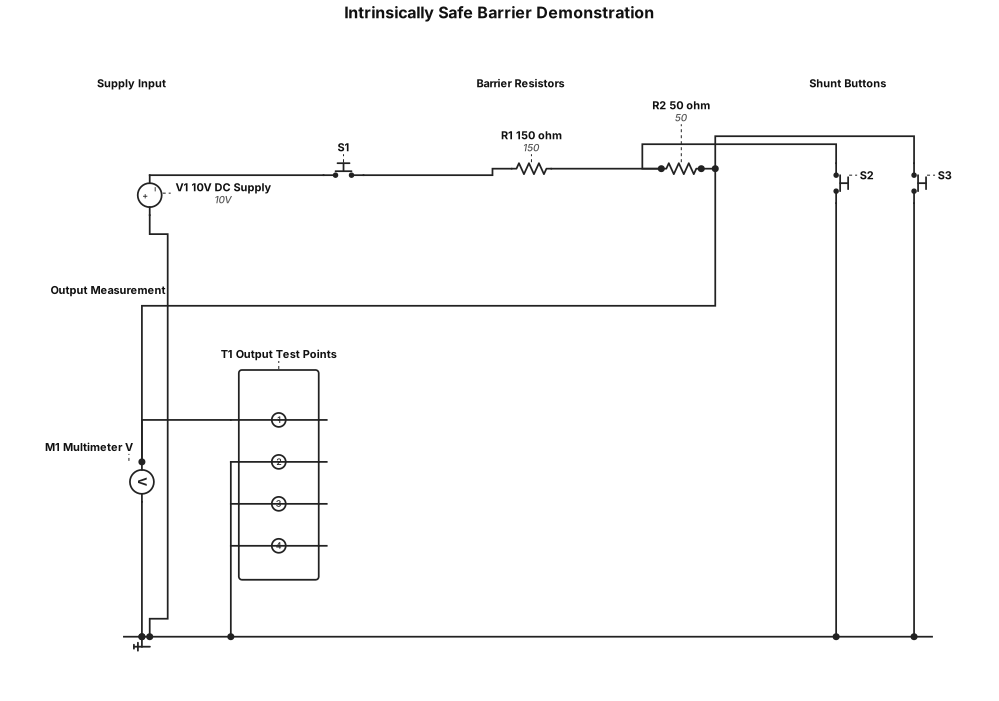
Create a beginner-friendly breadboard circuit based on an intrinsically safe barrier demonstration. Use a 10 V DC power supply, one 150 Ω resistor, one 50 Ω resistor, and three normally-open momentary push buttons. Do not use Arduino or any microcontroller. Show the exact breadboard hole connections, power rails, jumper wires, resistor positions, and multimeter probe positions. Label every component and connection clearly. Arrange the circuit as follows: push button S1 in series with the supply input, followed by the 150 Ω resistor and then the 50 Ω resistor. Connect push button S2 from the junction between the two resistors to the negative rail. Connect push button S3 from the output after the 50 Ω resistor to the negative rail. Connect the power supply negative terminal to the negative rail. Show how to measure output voltage using the multimeter. Generate an actual breadboard layout, not only a circuit schematic. Explain how the circuit behaves when each button is pressed. Flag any floating output or excessive current risks and recommend safe low-current test conditions.
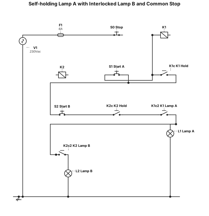
If you press S1, lamp A lights up and remains lit after you release it (self-holding). ● 2) Lamp B can only be switched on with S2 if lamp A is already lit. As long as A is not lit, S2 does nothing. 3) If you press S0 (common stop button), both lamps turn off — regardless of their state Make it with Neuter and L1
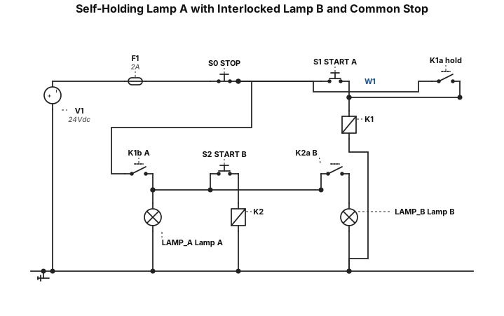
If you press S1, lamp A lights up and remains lit after you release it (self-holding). ● 2) Lamp B can only be switched on with S2 if lamp A is already lit. As long as A is not lit, S2 does nothing. 3) If you press S0 (common stop button), both lamps turn off — regardless of their state
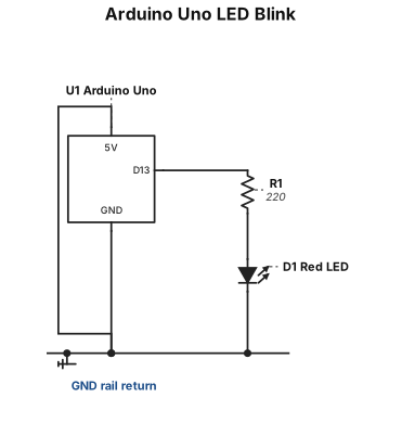
A breadboard wiring diagram for an Arduino Uno blinking one red LED from pin 13 through a 220 ohm resistor, with ground returned to the rail.