
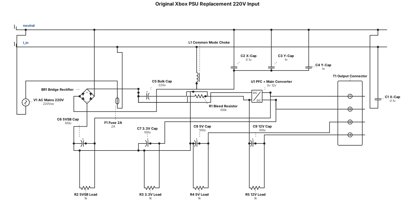
Original xbox psu replacement for 220v input
ENGINEERING DRAWING ARCHIVE · REAL SPECS
Engineering Diagram Examples from Real Specifications
Browse eligible circuit, ladder, single-line, P&ID, breadboard, timing, and logic drawings with their original prompts.
Browse 553 real creationsCOMMUNITY OUTPUTS · EXACT PROMPTS
All visitor creations
Showing 505–528 of 553. No stock examples or system defaults. Choose a tool, study a real result, then reopen its prompt as your starting point.
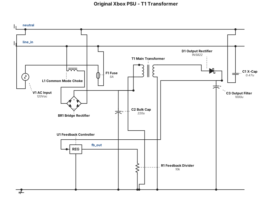
Original xbox psu replacement what is part t1 specs
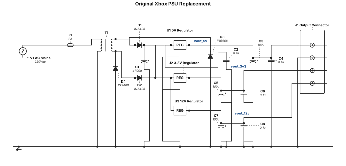
Original xbox psu replacement
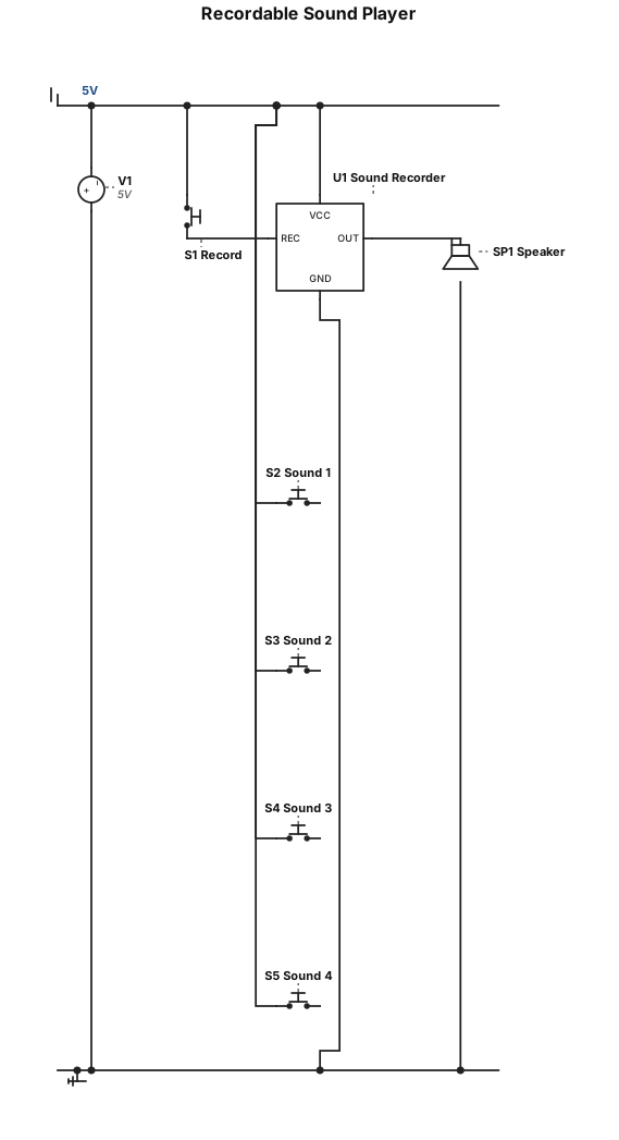
4 buttons to play different recordable sounds. 5v circuit. Record own sounds output to speaker
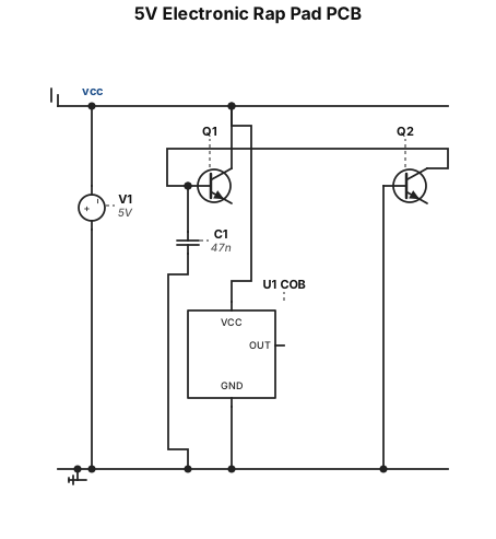
5v electronic rap pad PCB known components include one 2n2222 a331 transistor and a 47nf cap and a cob
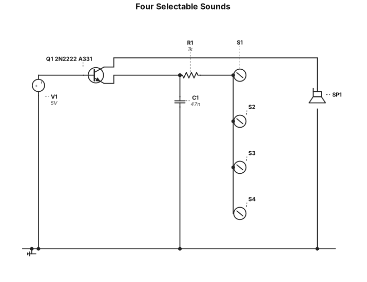
5v circuit four selectable sounds and a common signal. Sounds playback to speaker. has a single resistor. one 2n2222 a331 transistor and a 47nf capacitor no other components
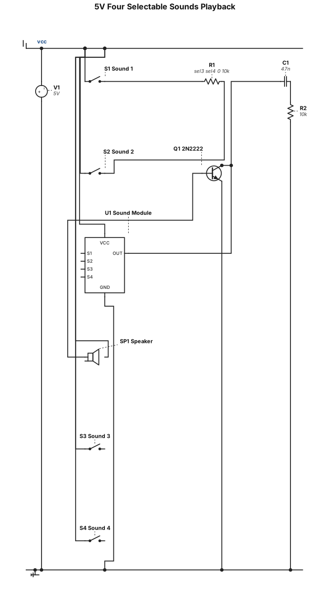
5v circuit four selectable sounds playback to speaker has a single resistor one 2n2222 a331 transistor and a 47nf capacitor

Create a clear preliminary electronics interconnection schematic for the HSI portable imaging research system. Known equipment: - Raspberry Pi 5 (4 GB) - Raspberry Pi Camera Module 3 - 7-inch touchscreen display - 64 GB microSD card - External power supply; exact model and electrical rating still need verification Show only connections that can be supported by the selected hardware documentation: - Camera Module 3 connected to the Raspberry Pi through the compatible camera interface. - microSD storage associated with the Raspberry Pi. - Touchscreen display connected through its verified interface, to be confirmed from the exact display model. - Power input to the Raspberry Pi and any separate display power input only after their required ratings and wiring have been verified. Use standard schematic symbols, clearly labelled components, distinct power/data connections and a legend. Do not guess GPIO pins, connector pin numbers, display interface, voltage/current ratings, grounding, regulator circuitry or wiring. Mark unverified connections as “TO VERIFY — exact model/datasheet required” instead of drawing fabricated connections. Title the drawing “HSI System — Preliminary Electronics Interconnection Diagram”. Add a note: “For presentation planning only. Verify against the actual hardware, manufacturer datasheets and physical wiring before use.” Do not include the Ocean QE Pro-ABS spectrometer in the device circuit because it is separate calibration/validation equipment.
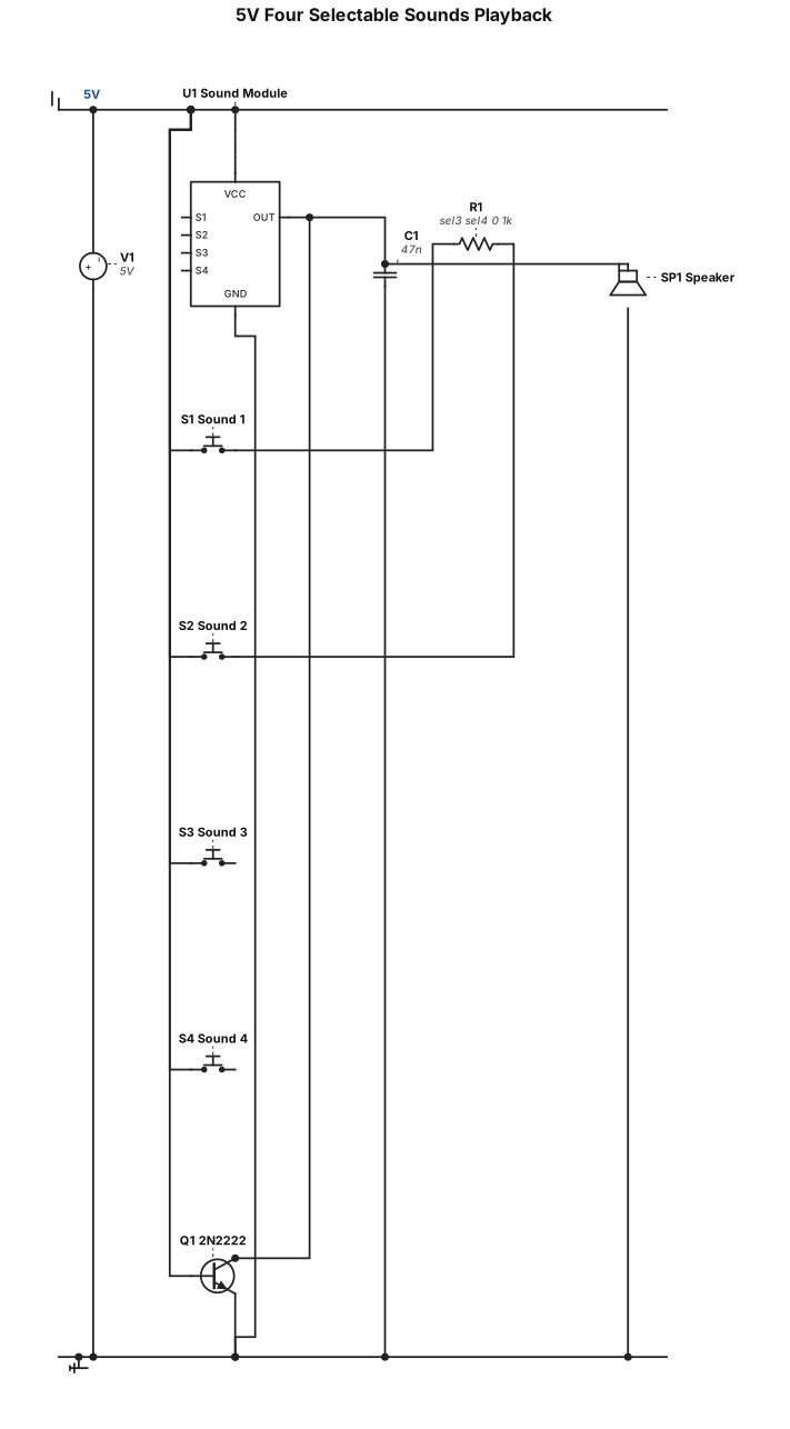
5v circuit four selectable sounds playback to speaker has a single 1k resistor one 2n2222 a331 transistor and a 47nf capacitor
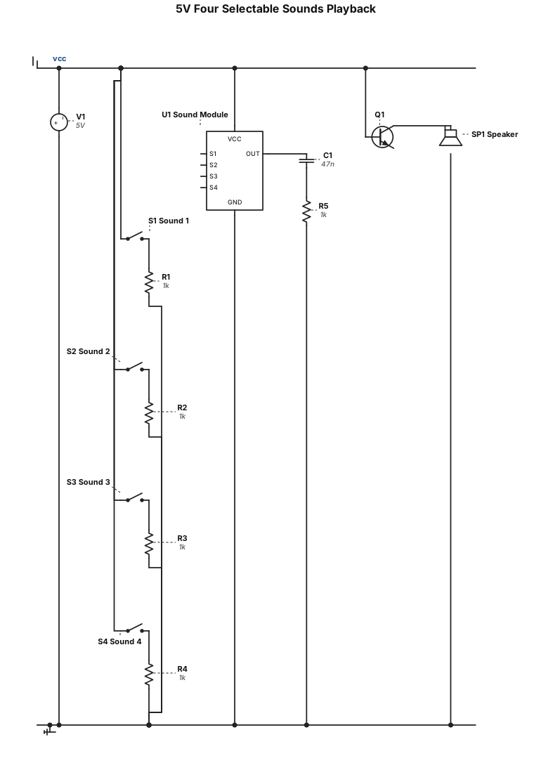
5v circuit four selectable sounds playback to speaker has a 1k resistor one 2n2222 a331 transistor and a 47nf capacitor
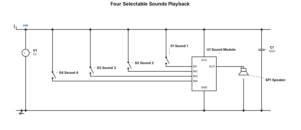
5v circuit four selectable sounds playback to speaker
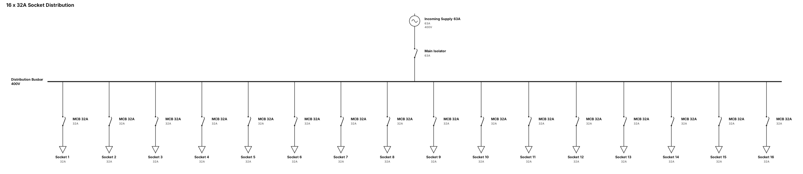
I want 16 no's 32A socket my incoming size 63A
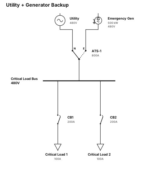
A 480 V utility and 500 kW emergency generator feeding an 800 A automatic transfer switch, then a critical-load bus with two 200 A breakers and two 100 A loads.
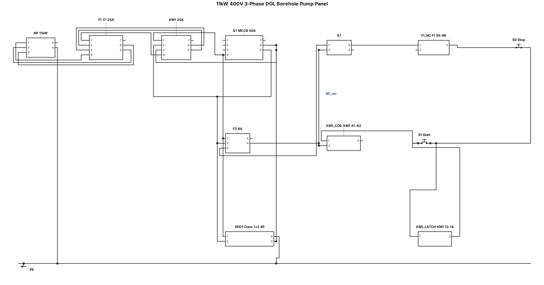
Generate a 2D IEC 60617 electrical schematic for an 11 kW 400V 3-Phase DOL Borehole Pump Panel. POWER CIRCUIT (400VAC 3-Phase + PE, No Neutral): - Terminals L1, L2, L3, PE. - Main Breaker Q1 (50A 3P MCCB). - Surge Protector SPD1 (Class 1+2 4P) downstream of Q1 across L1, L2, L3 to PE. - Contactor KM1 (25A 3P) feeding Thermal Overload F1 (17-25A). - Motor terminals U1, V1, W1 feeding 11 kW Motor M1 with frame PE ground. CONTROL CIRCUIT (400VAC L1-L2 Supply): - Control MCB F2 (6A 2P) across L1 and L2. - Phase Angle/Sequence Relay K1 (NO contact 11-14) in series. - Thermal Overload F1 (NC contact 95-96) in series. - NC Stop Button S0 in series. - NO Start Button S1 in parallel with KM1 NO Latch (13-14). - 400VAC Contactor Coil KM1 (A1-A2) back to L2 via F2
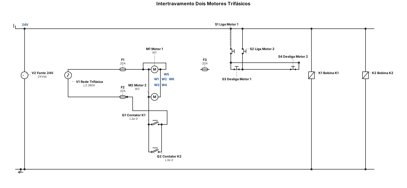
faça um diagrama de intertravamento com dois motores trifásico
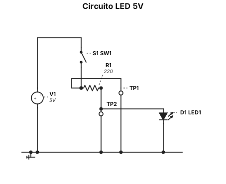
un circuito LED da 5 V con una resistenza in serie da 220 Q, un interruttore SPST e punti di test prima e dopo la resistenza
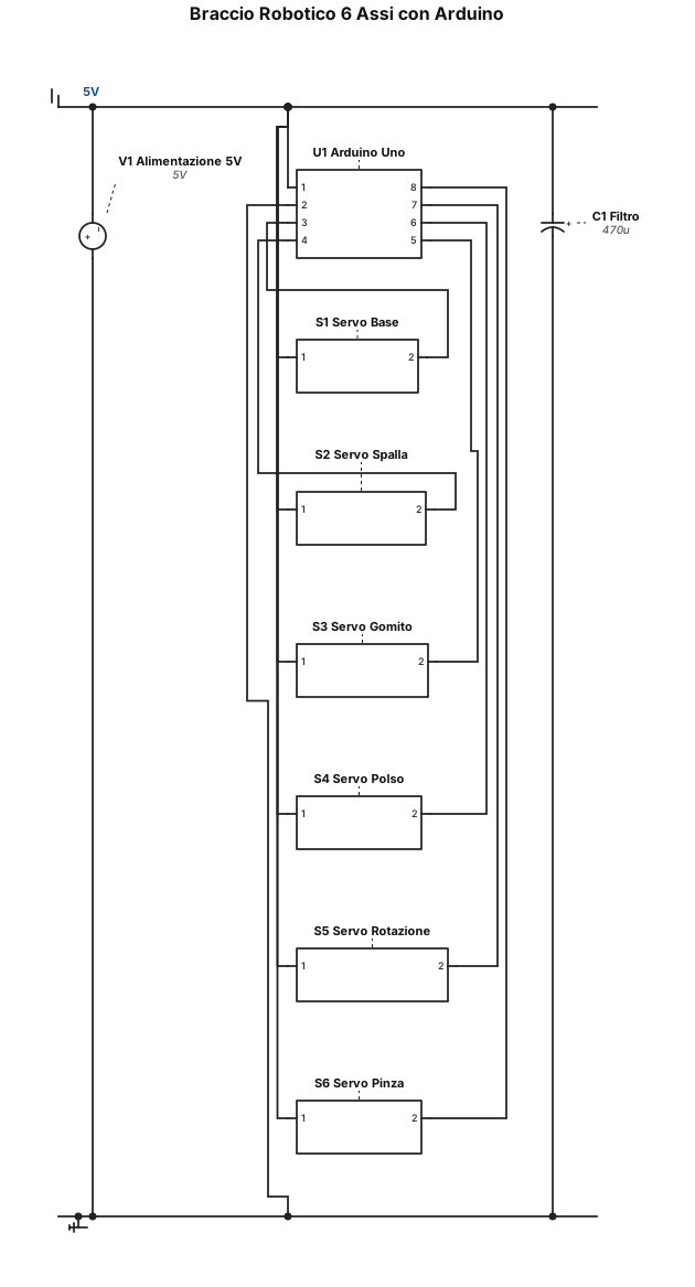
circuito per un braccio robotico a 6 assi con arduino e servomotori
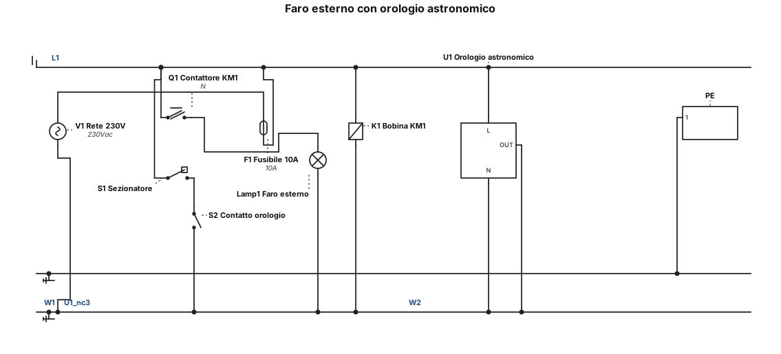
devo fare un circuito di potenza e di comando di un faro esterno comandato di notte da un orologio astronomico
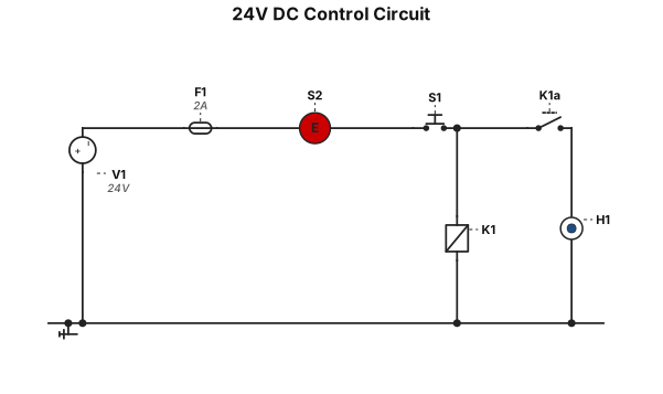
A 24 V DC control circuit with a fuse, emergency stop, start pushbutton, relay coil, seal-in contact, and one pilot lamp that turns on with the relay.
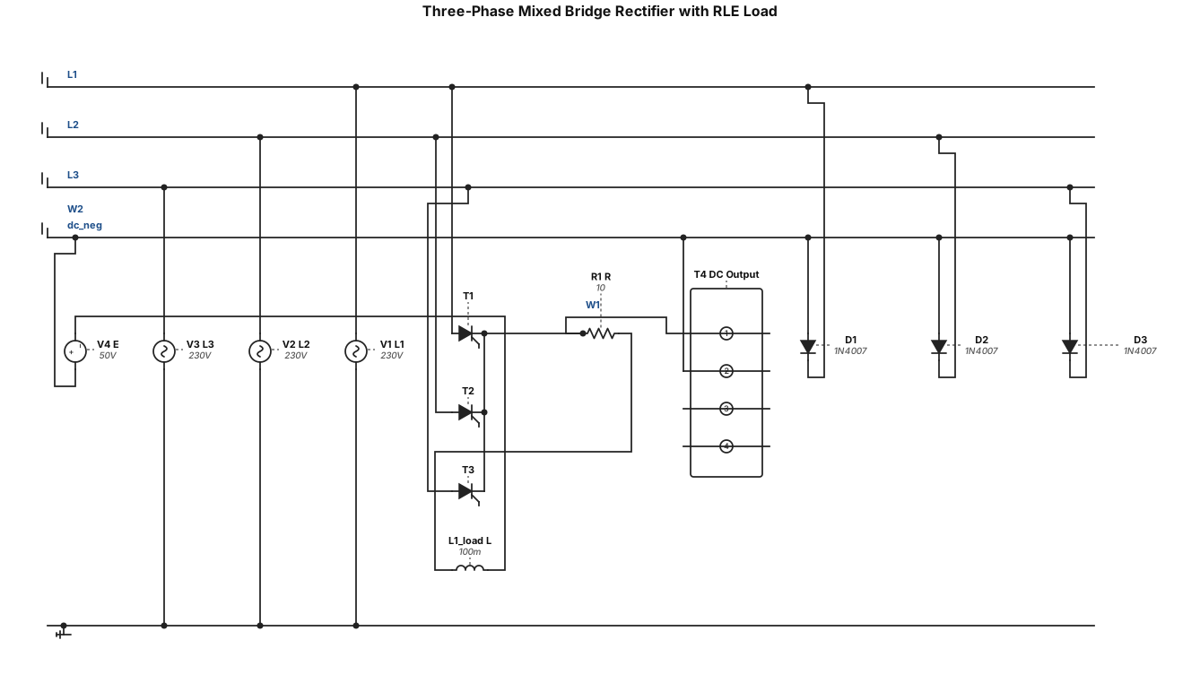
Draw a clear electrical power circuit of a three-phase mixed bridge rectifier (semi-controlled six-pulse rectifier) supplying an RLE load. Use three-phase AC inputs L1, L2 and L3, three thyristors in the upper arm, three diodes in the lower arm, and a series R-L-E load connected across the DC output terminals. Label all components and show the DC output polarity. Use standard electrical symbols on a white background.
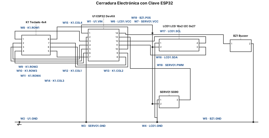
Crea un esquemático de un sistema de cerradura electrónica con clave usando una ESP32 DevKit (30 pines). Usa únicamente las conexiones listadas, sin agregar componentes ni conexiones adicionales. COMPONENTES: - ESP32 DevKit - Teclado matricial 4x4 - Pantalla LCD 16x2 con módulo I2C (dirección 0x27) - Micro servomotor SG90 - Buzzer activo - Protoboard (rieles de alimentación + y −) ALIMENTACIÓN: - La ESP32 se alimenta por USB. - Pin GND de la ESP32 → riel negativo (−) - Pin VIN (5V) de la ESP32 → riel positivo (+) - Todos los GND del circuito deben compartir una tierra común. CONEXIONES: Teclado matricial 4x4 (directo a la ESP32, sin alimentación): - Fila 1 → GPIO13 - Fila 2 → GPIO12 - Fila 3 → GPIO14 - Fila 4 → GPIO27 - Columna 1 → GPIO26 - Columna 2 → GPIO25 - Columna 3 → GPIO33 - Columna 4 → GPIO32 Pantalla LCD I2C: - GND → riel negativo (−) - VCC → riel positivo (+) (5V) - SDA → GPIO21 - SCL → GPIO22 Servomotor SG90: - Cable café (GND) → GND de la ESP32 - Cable rojo (V+) → riel positivo (+) (5V) - Cable naranja (señal PWM) → GPIO15 Buzzer: - Positivo (+) → GPIO4 - Negativo (−) → riel negativo (−) REQUISITOS: - Etiqueta cada net con su nombre (5V, GND, SDA, SCL, ROW1–ROW4, COL1–COL4, SERVO_PWM, BUZZER). - Organiza el esquemático con la ESP32 al centro y los periféricos alrededor. - Verifica que no haya pines sin conectar ni cortocircuitos entre 5V y GND. - Al final, genera una lista de conexiones (netlist) para que pueda comprobarla.
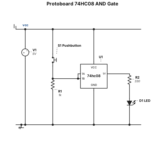
Crie um layout de protoboard detalhado para um circuito de lógica digital usando o CI 74HC08, uma chave pushbutton, um resistor de 1 kΩ, um LED, um resistor de 330 Ω e alimentação de 5 V. Mostre a posição física de cada componente, os números dos pinos do CI, as coordenadas dos furos e cada fio. Siga este circuito: a chave fornece o sinal de entrada para as duas entradas da primeira porta AND; o resistor de 1 kΩ mantém a entrada em nível baixo quando a chave está aberta; a saída da porta AND aciona o LED em série com o resistor de 330 Ω. Inclua as ligações de alimentação e GND e confira a pinagem do 74HC08.
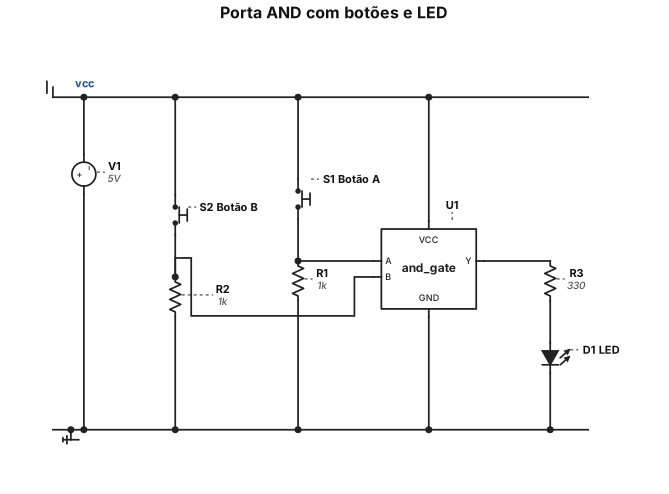
Monte o circuito na protoboard seguindo as orientações: • Conecte cada entrada da porta AND a um botão (push button) e a um resistor de 1 kΩ ligado ao GND (pull-down): quando o botão não estiver pressionado, a entrada estará em nível lógico 0; quando pressionado, a entrada será levada a +5 V (nível lógico 1). • Conecte a saída da porta AND a um LED em série com um resistor de 330 Ω, ligado ent
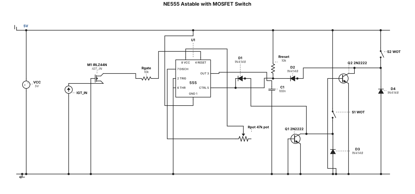
NE555 timer astable circuit with MOSFET switch. Components: NE555 IC (8-pin), IRLZ44N N-MOSFET, two 2N2222 NPN transistors, four 1N4148 diodes, one WOT switch. 555 pins 2+6 to 47k pot and 100nF cap. Pin 3 through 10k to MOSFET gate. Pin 4 pulled to 5V through 10k, two diodes from transistor collectors into pin 4. MOSFET drain to IGT_IN, source to IGT_OUT and GND.