
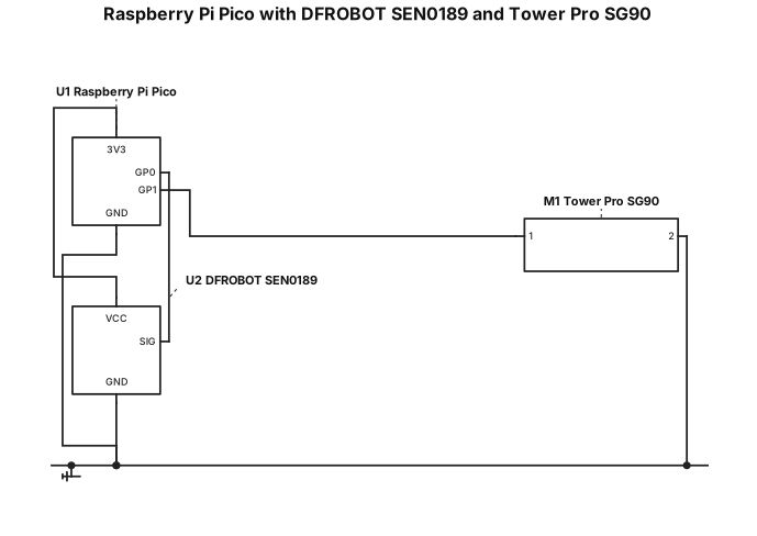
A raspberry Pi Pico connected to a DFROBOT SEN0189 and Tower Pro SG90
ENGINEERING DRAWING ARCHIVE · REAL SPECS
Engineering Diagram Examples from Real Specifications
Browse eligible circuit, ladder, single-line, P&ID, breadboard, timing, and logic drawings with their original prompts.
Browse 543 real creationsCOMMUNITY OUTPUTS · EXACT PROMPTS
All visitor creations
Showing 193–216 of 543. No stock examples or system defaults. Choose a tool, study a real result, then reopen its prompt as your starting point.
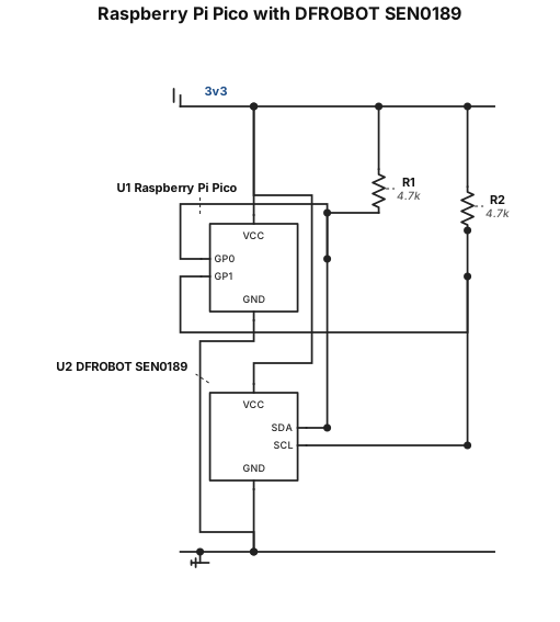
A raspberry Pi Pico connected to a DFROBOT SEN0189
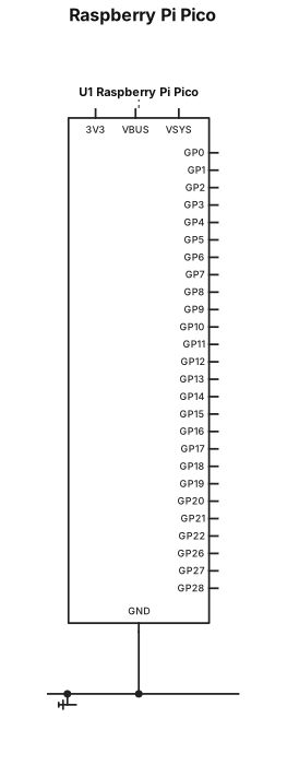
A raspberry Pi Pico
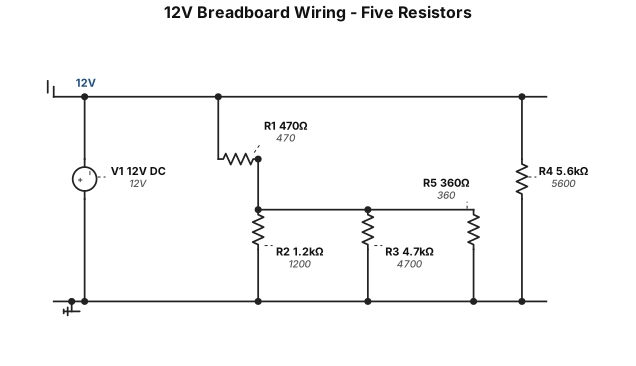
Create a breadboard wiring diagram for a 12V DC circuit using five resistors. R1 = 470 ohms, R2 = 1200 ohms, R3 = 4700 ohms, R4 = 5600 ohms, R5 = 360 ohms. Connect R4 directly between 12V positive and ground. Connect R1 from 12V positive to junction B. Connect R2, R3, and R5 in parallel between junction B and ground. Show a realistic solderless breadboard with exact numbered holes, correct resistor colour bands, and coloured jumper wires. Label every resistor and connection. Do not generate only a schematic.

Нарисуй полноценную электрическую принципиальную схему по следующим условиям. Используй стандартные электрические символы IEC и оформи чертёж как настоящую промышленную электрическую схему, а не блок-схему. 1. Ввод питания * Вводной кабель: 5×10 мм². * Главный выключатель: S1. * Автоматический выключатель: F1, 3-полюсный, B10 A. * Блок питания T1: 24 V DC. 2. Двигатель M1 * Двигатель M1 мощностью 2,2 kW. * Защитный аппарат Q1. * Контакторы K1 и K2. * Трёхпозиционный переключатель. * Кабель переключателя: 4×1,0 мм². 3. Двигатель M2 * Защитный аппарат Q2. * Частотный преобразователь A1. * Двигатель M2 мощностью 11 kW. * Трёхпозиционный переключатель и потенциометр. * Кабель двигателя: 4×4 мм². 4. Цепь безопасности * Реле безопасности с четырьмя кнопками аварийного останова E-STOP. * Два канала безопасности CH1 и CH2 проходят через кнопки E-STOP. * Реле R1 отключает три линии питания 24 V DC. Требования к результату: * Покажи все элементы и реальные электрические соединения между ними. * Отдельно отобрази силовые цепи, цепи управления и цепь безопасности. * Подпиши элементы, контакты, проводники, кабели и напряжения. * Используй стандартные условные обозначения контакторов, двигателей, автоматов, реле, переключателей и частотного преобразователя. * Сделай аккуратный технический чертёж, похожий на схемы из учебника по промышленной электротехнике. * Результат предоставь в формате PDF или SVG с высоким качеством и возможностью увеличения. Важно: не создавай блок-схему и не заменяй электрические соединения стрелками. Не придумывай отсутствующие данные. Если для правильной схемы не хватает информации, укажи, что именно нужно уточнить. Проверь правильность соединений и обозначений. Не утверждай, что схема полностью корректна, если это не проверено.
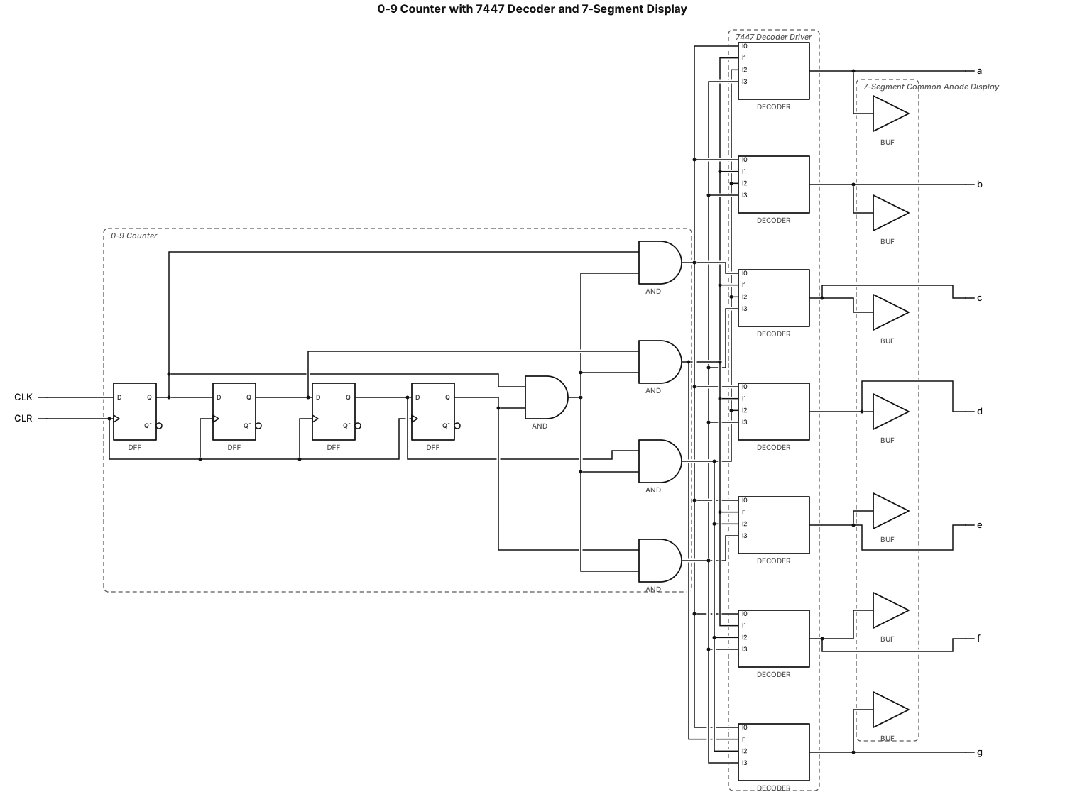
create a flip flop counter from 0 to 9 ,connect the outputs to one and one only integrate circuit 7447 decoder driver and a then use a seven segments common anode display to visualize the counting
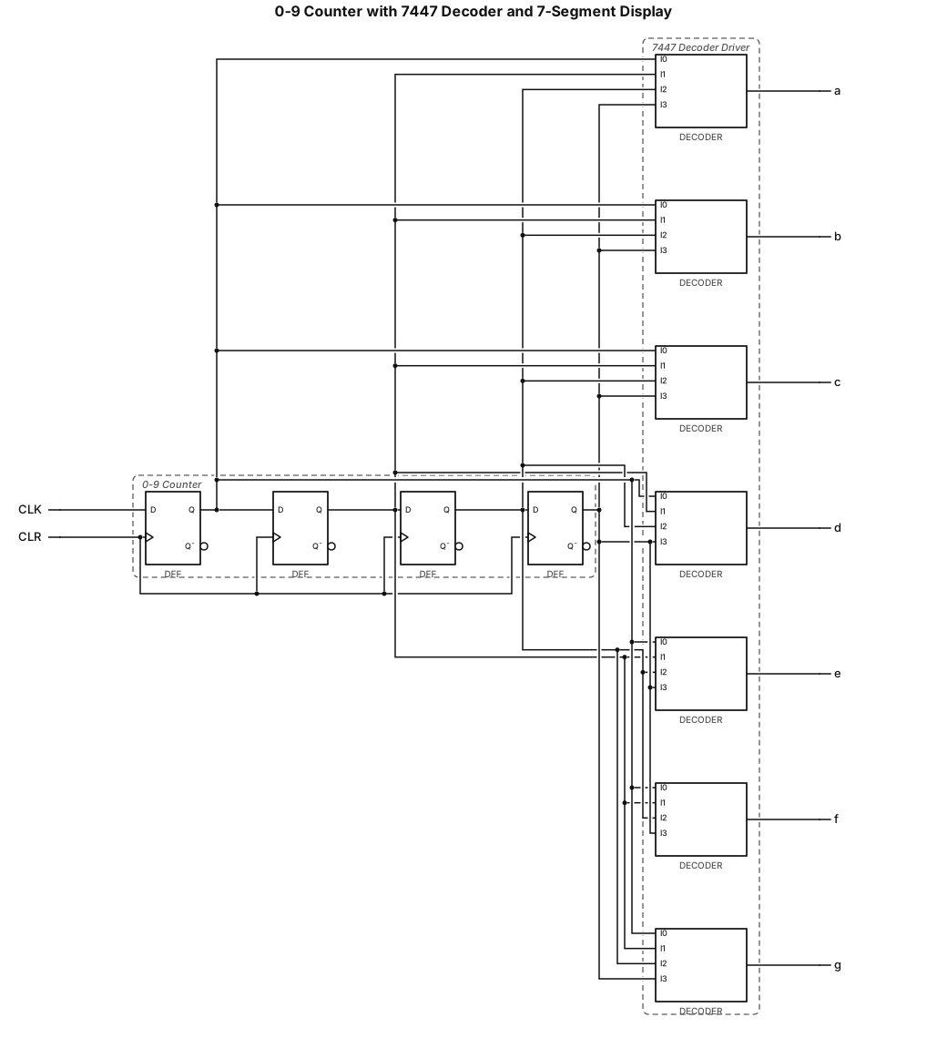
create a flip flop counter from 0 to 9 ,connect the outputs to one and one only 7447 decoder driver and a then use a seven segments common anode display to visualize the counting

multiplexer con 8 ingressi
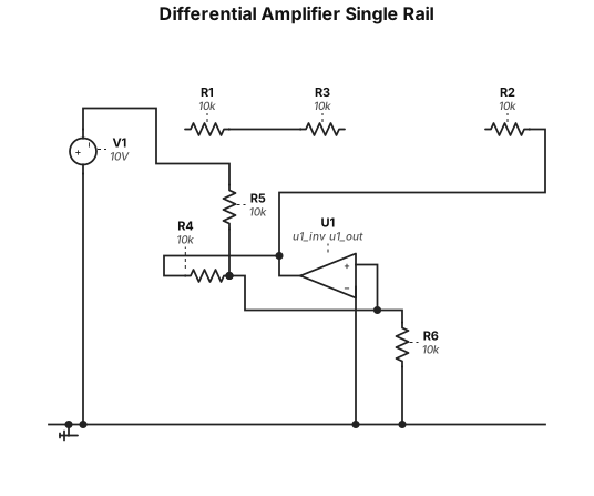
Differential amplifier with O.A. single rail +10V
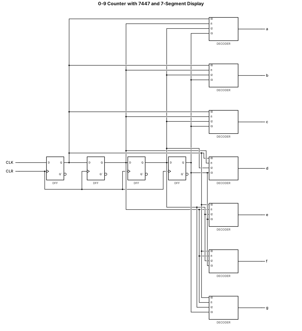
create a flip flop counter from 0 to 9 ,connect the outputs to one 7447 decoder driver and a then use a seven segments common anode display to visualize the counting
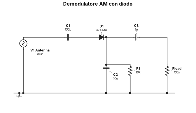
demudulatore am con diodo
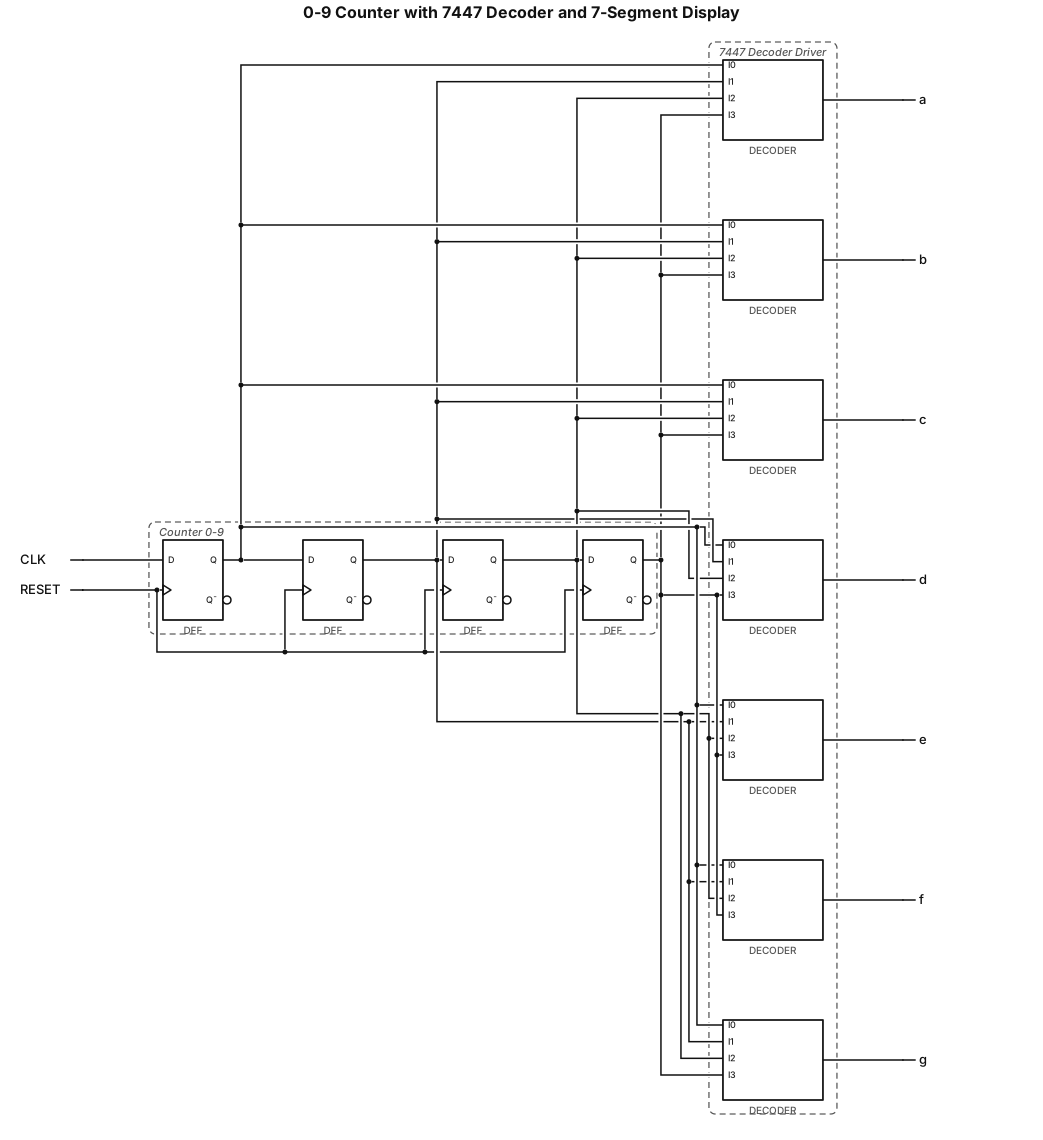
create a flip flop counter from 0 to 9 ,connec the outputs to a 7447 decoder driver and a then use a seven segments common anode display to visualize the counting
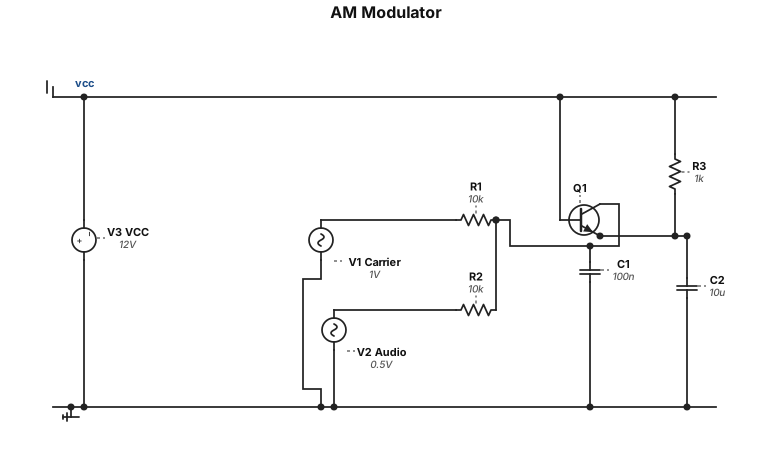
am modulator
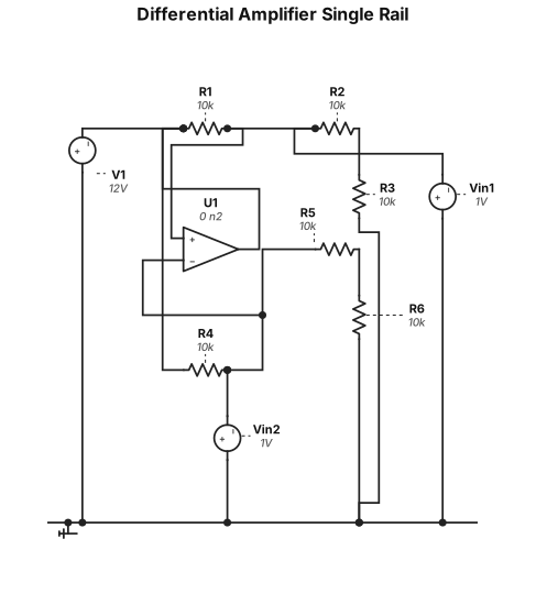
Differential amplifier with O.A. single rail
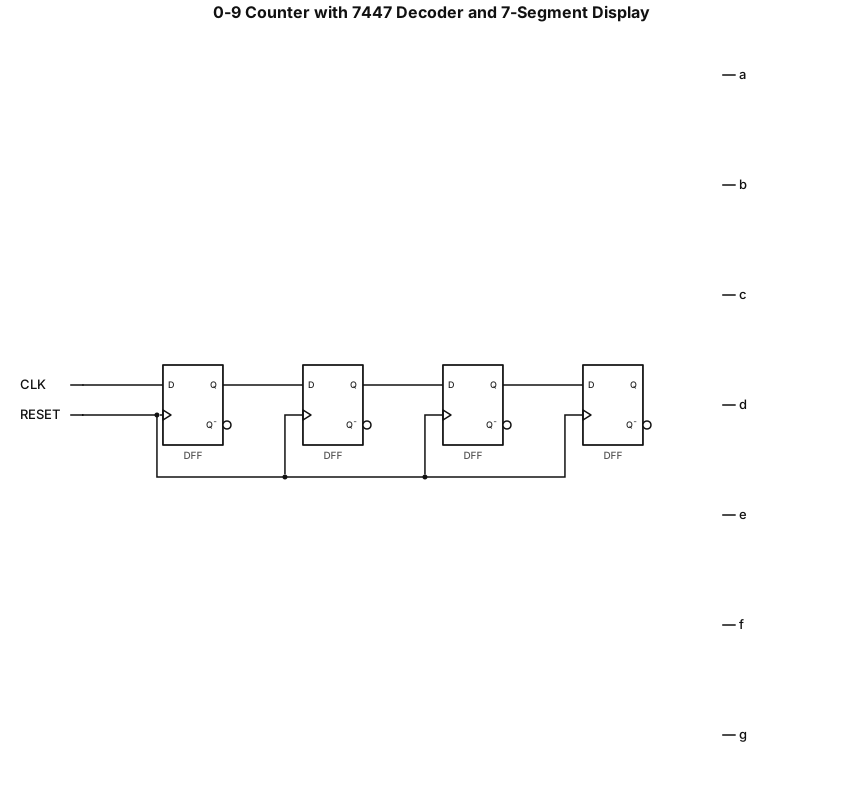
create a flip flop counter from 0 to 9 using a 7447 decoder driver and a seven segments common anode display to visualize the counting
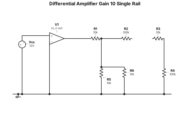
Differential amplifier gain 10 with A.O. single rail show operational amplifier power supply
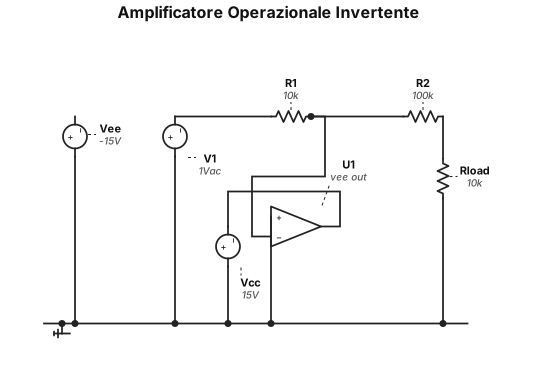
amplificatore operazionele invertente
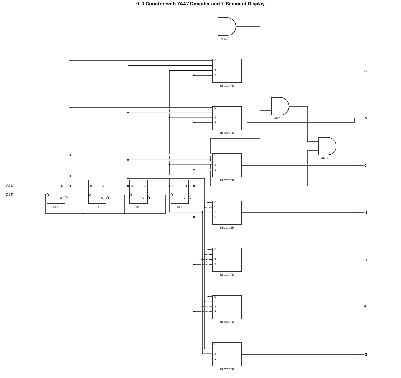
a flip flop counter from 0 to 9 and a 7447 decoder driver with seven segments display
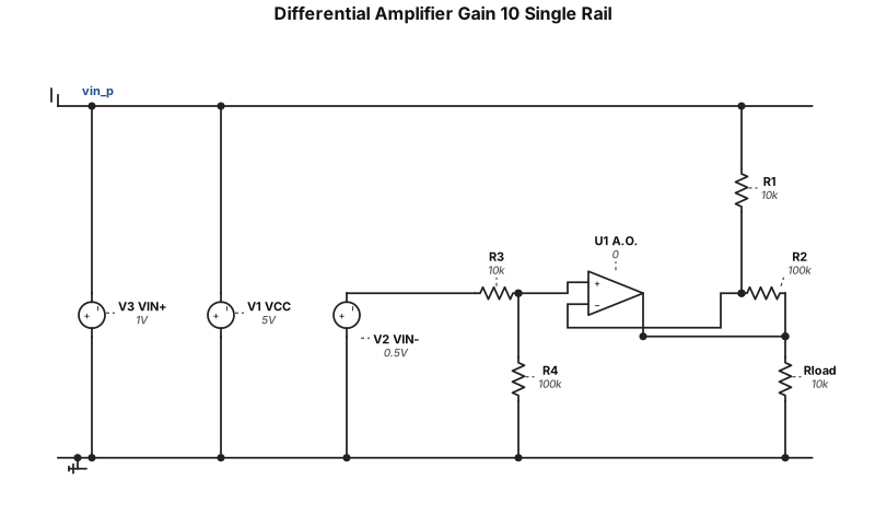
Differential amplifier gain 10 with A.O. single rail show A.O. power supply
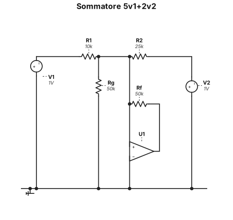
realizza la funzione 5v1+2v2 con amplificatori operazionali
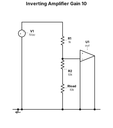
Draw inverting amplifier with gain =10
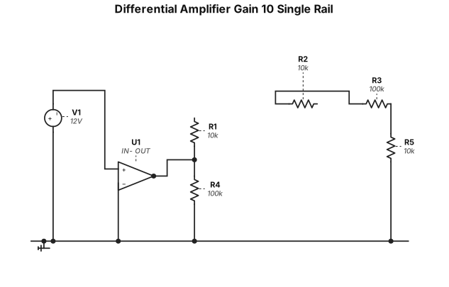
Differential amplifier gain 10 with A.O. single rail show power supply
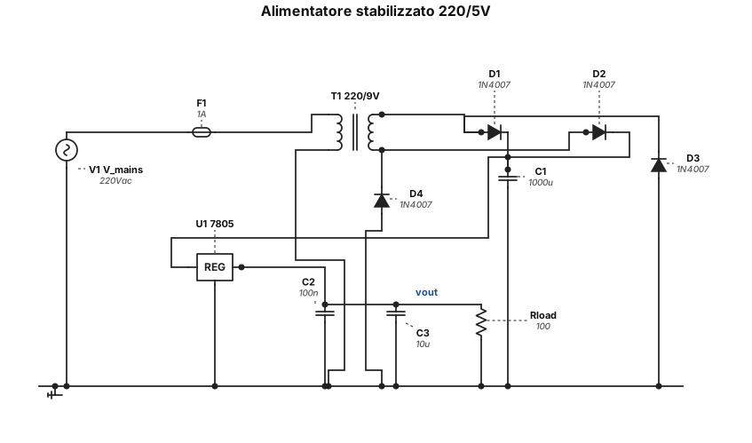
alimentatore stabilizzato 220/5 V
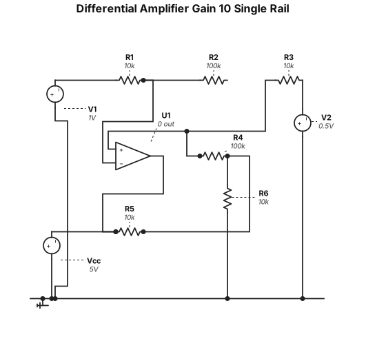
Differential amplifier gain 10 with A.O. single rail